Stator for rotary electrical machine

A technology for rotating electrical machines and stators, which is applied in the field of stators and can solve the problems of increasing and increasing the size of the stators.

Inactive Publication Date: 2011-09-28
AISIN SEIKI KK
View PDF4 Cites 64 Cited by
  • Summary
  • Abstract
  • Description
  • Claims
  • Application Information

AI Technical Summary

Problems solved by technology

Therefore, the size of the power supply portion in the axial direction tends to increase, which further leads to an increase in the size of the stator

Method used


Image

  • Stator for rotary electrical machine
  • Stator for rotary electrical machine
  • Stator for rotary electrical machine

Examples


no. 1 example

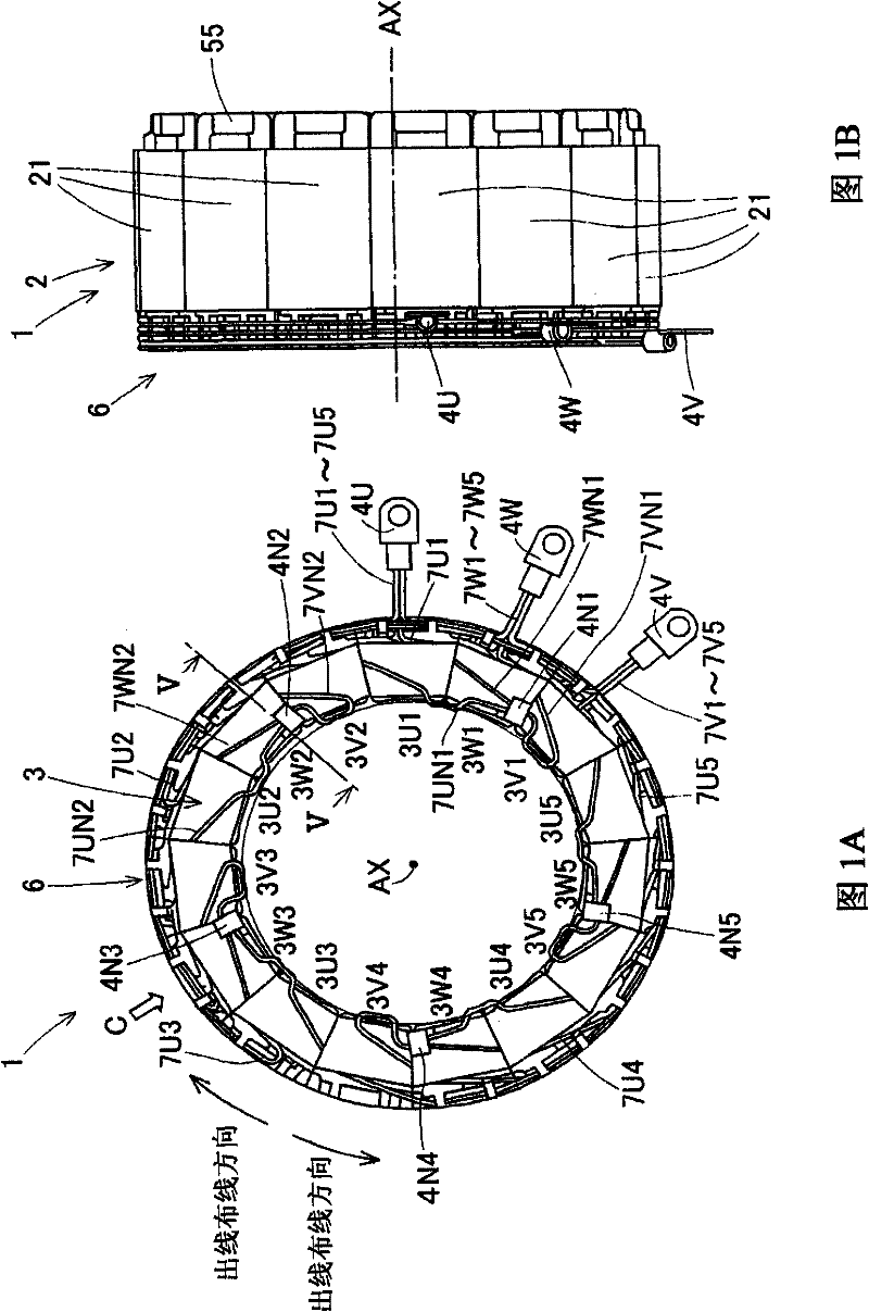
[0038] Below, with reference to Figures 1 to 1 in the accompanying drawings Figure 6 , illustrates the stator 1 of the rotating electrical machine according to the first embodiment. Figure 1A and Figure 1B Shown is a diagram for explaining the stator 1 of the rotating electric machine according to the first embodiment. in particular, Figure 1A Shown is a plan view of the stator 1 of the rotating electric machine according to the first embodiment, as viewed in the direction in which its axis AX extends. Figure 1B Shown is a side view of the stator 1 of the electric rotating machine according to the first embodiment. The electric rotating machine is configured such that the stator 1 is arranged on the outer peripheral portion of the electric rotating machine, and the rotor is arranged on the radially inner side of the stator 1 . In addition, the rotary electric machine is formed approximately symmetrically with respect to the axis AX. As shown in FIG. 1 , a stator 1 incl...

no. 2 example

[0064] Below, refer to Figure 9 The stator 10 of the rotating electrical machine of the second embodiment will be described. The stator 10 of the electric rotating machine according to the second embodiment differs from the stator 1 of the electric rotating machine according to the first embodiment in the groove portion formed at the power supply insulating portion 80 which is formed at the same angle as that formed at the power supply insulating portion 8 . The groove portions 86U, 86V, and 86W have different shapes. In the second embodiment, differences between the stator 1 of the rotating electrical machine according to the first embodiment and the stator 10 of the rotating electrical machine according to the second embodiment will be mainly explained. Figure 9 Shown is a sectional view of a stator 10 of a rotating electric machine according to a second embodiment. The basic configuration of the stator 10 according to the second embodiment is the same as that described ...


PUM


Abstract

A stator (1, 10) for a rotary electrical machine, includes a stator core (2) in a cylinder shape and having plural magnetic pole teeth (22), which are arranged in a circumferential direction of the stator while keeping a distance therebetween and each of which protrudes in a radial direction of the stator core, a coil (3) configured with a conductive wire wound around each of the magnetic pole teeth, an insulating bobbin (5) provided between the coil and the corresponding magnetic pole tooth, and an electric power supply portion (6, 60) arranged axially outwardly of the stator core, electrically connecting the coil with an outside of the stator, and including an outgoing wire (7U1, 7U2, 7U3, 7U4, 7U5, 7V1, 7V2, 7V3, 7V4, 7V5, 7W1, 7W2, 7W3, 7W4, 7W5), which corresponds to a portion of at least one of a winding start and a winding end of the conductive wire being extended by a predetermined length, and an isolating member (8, 80) having a groove portion (86U, 86V, 86W, 96U, 96V, 96W) for accommodating and guiding the corresponding outgoing wire.

Description

technical field [0001] The present invention relates to a stator for a rotating electrical machine such as an electric motor, generator or the like. In particular, the present invention relates to a power supply configuration for supplying power to a stator coil. Background technique [0002] In general, a rotating electric machine (such as a generator installed in a hybrid vehicle, an electric vehicle, etc.) is configured to have a rotating field type inner rotor such that a stator having coils is arranged on the outer peripheral side, and a rotor having magnets is arranged on the outer peripheral side of the stator. Radially inside. A rotating electric machine stator having the above-mentioned configuration generally includes: a cylindrical stator core having a plurality of magnetic pole teeth each protruding in a radially inward direction; a coil in such a manner that a wire is wound around each magnetic pole tooth constituted; and, an insulating bobbin formed in a cyli...

Claims


Application Information

Patent Timeline
Patent Type & Authority Applications(China)
IPC IPC(8): H02K1/14H02K3/28H02K3/34H02K3/38
CPCH02K3/28H02K3/522H02K2203/06
Inventor 加藤功
Owner AISIN SEIKI KK
Why Eureka
Try Eureka