Split core status indicator

a split core and status indicator technology, applied in the direction of inductances, magnetic core inductances, instruments, etc., can solve the problems of complex monitoring of the operation of these devices, impracticality of monitoring the state of the switch, and small devices consuming very limited curren

Active Publication Date: 2009-05-07
VERIS INDS
View PDF105 Cites 65 Cited by
  • Summary
  • Abstract
  • Description
  • Claims
  • Application Information

AI Technical Summary

Problems solved by technology

Many industrial, commercial and residential environments incorporate large numbers of electrical loads that are widely distributed geographically and often located in sites where access is difficult.
Many these devices are small and draw very limited amounts of current, often only a small fraction of an amp.
Although desirable, monitoring the operation of these devices is complicated by their remoteness from the monitoring location.
The state of the switch controlling the operation of a load can sometimes be signaled to a remotely located monitoring station, but the additional wiring and circuit complexity often makes monitoring the state of the switch impractical.
However, the cost a switch with a ...

Method used


Image

  • Split core status indicator
  • Split core status indicator
  • Split core status indicator

Examples


Embodiment Construction

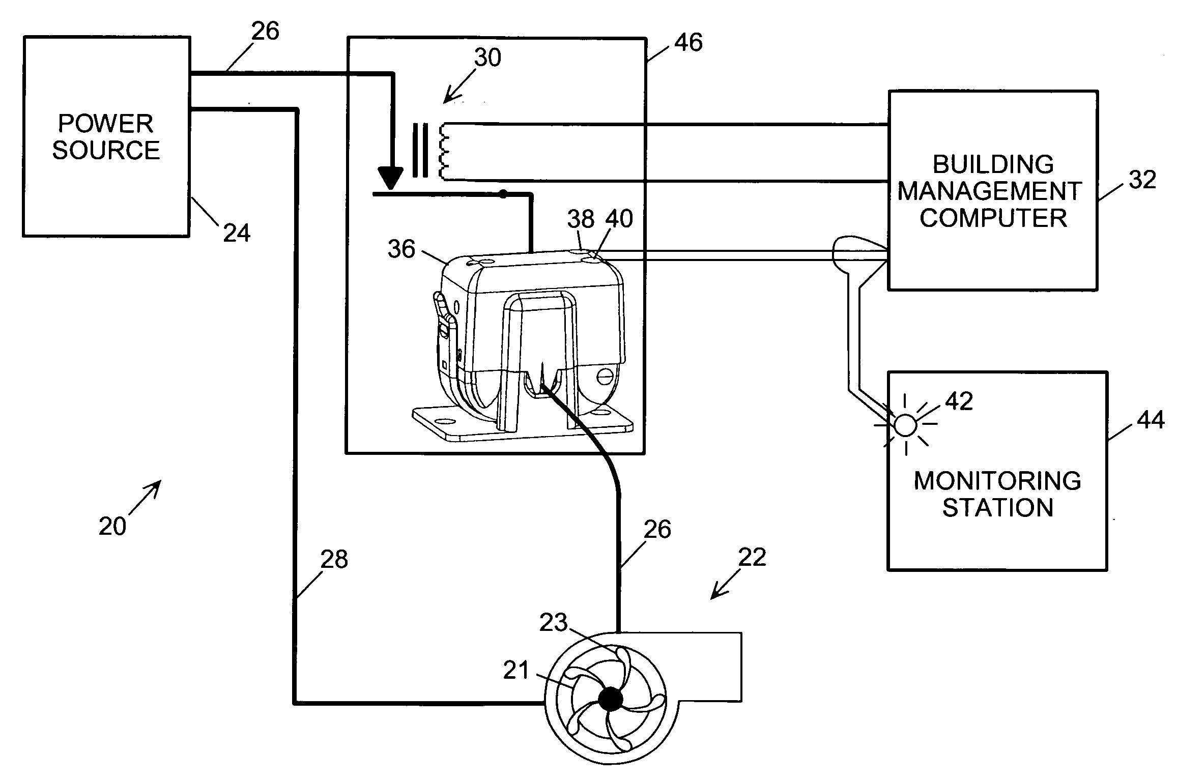
[0015]Referring in detail to the drawings where similar parts are identified by like reference numerals and referring more particularly to FIG. 1, an exemplary electrical system 20 includes an electrical load 22 that is connected to a power supply 24 by power cables 26, 28. By way of examples, loads may include valves, heaters, relays, lights, and motors that drive pumps, fans, etc. In the exemplary system, the load comprises a motor 21 that drives a fan 23. The operation of the motor of the exemplary system is controlled by a relay 30 which, in turn, is controlled by a building management controller 32. A status indicator 36 comprising generally a current transformer to sense current in a power cable and a current switch that is actuated by the output of the current transformer, monitors the current flow in one of the power cables. When the fan motor 22 is running and current is flowing to the fan motor in the power cable 26, the status indicator provides a first signal at the outp...


PUM


Abstract

The size of a status indicator for monitoring a current in a power cable is reduced by integrating a bobbin for the secondary winding with a current transformer core and integrating a circuit board including output terminals with a current transformer assembly.

Description

CROSS-REFERENCE TO RELATED APPLICATIONS[0001]This application claims the benefit of U.S. Provisional App. No. 60 / 993,330, filed Sep. 10, 2007.BACKGROUND OF THE INVENTION[0002]The present invention relates to a device for indicating the operating state of an electrical load and, more particularly, to a device for monitoring electric current in a cable connecting a load and a power source.[0003]Many industrial, commercial and residential environments incorporate large numbers of electrical loads that are widely distributed geographically and often located in sites where access is difficult. Many these devices are small and draw very limited amounts of current, often only a small fraction of an amp. However, the operation of these loads, for example, small fan motors or lights can be important to maintaining a safe environment or the successful completion of a process that may involve costly or hazardous equipment or materials. Although desirable, monitoring the operation of these devi...

Claims


Application Information

Patent Timeline
IPC IPC(8): G01R15/18H01F27/00
CPCH01F38/30G01R15/186
Inventor BERNKLAU, JAMES
Owner VERIS INDS
Why Eureka
Try Eureka