Vehicle power cables retaining structure

a technology of power cables and retaining structures, which is applied in the direction of mechanical equipment, electric propulsion mounting, transportation and packaging, etc., can solve the problems of large useless space, difficult formation of such a complexly shaped cover, and relative weight, and achieve the effect of increasing the surface area of the fin

Inactive Publication Date: 2005-01-20
HONDA MOTOR CO LTD
View PDF6 Cites 99 Cited by
  • Summary
  • Abstract
  • Description
  • Claims
  • Application Information

AI Technical Summary

Benefits of technology

[0027] According to the construction, the surface area of the fin can be increased.

Problems solved by technology

A power cable for supplying power from a battery to a driving motor in an electric vehicle has relatively thick in diameter and is hence relatively heavy in weight.
However, in the event that the plurality of power cables are surrounded collectively by the protection cover in the conventional fashion, a large useless space is created within the protection cover, and this leaves a problem to be solved from a viewpoint of effective use of a space above the floor.
In addition, a route along which the power cables are laid out is not always simply linear but may become sometimes complex due to rises and bends, and in the event that the protection cover is attempted to be mounted along the power cables which are routed complexly, the protection cover itself has to be formed into a complex shape accordingly, and the formation of such a complexly shaped cover becomes difficult.
Additionally, there occurs a case which requires the protection cover to be divided into a plurality of portions, and this makes troublesome the mounting of the protection cover so divided, the workability and productivity being thereby deteriorated.

Method used


Image

  • Vehicle power cables retaining structure
  • Vehicle power cables retaining structure
  • Vehicle power cables retaining structure

Examples


first embodiment

[0040] (First Embodiment)

[0041] Firstly referring to FIGS. 1 to 7, a first embodiment of a vehicle cable powers retaining structure according to the invention will be described.

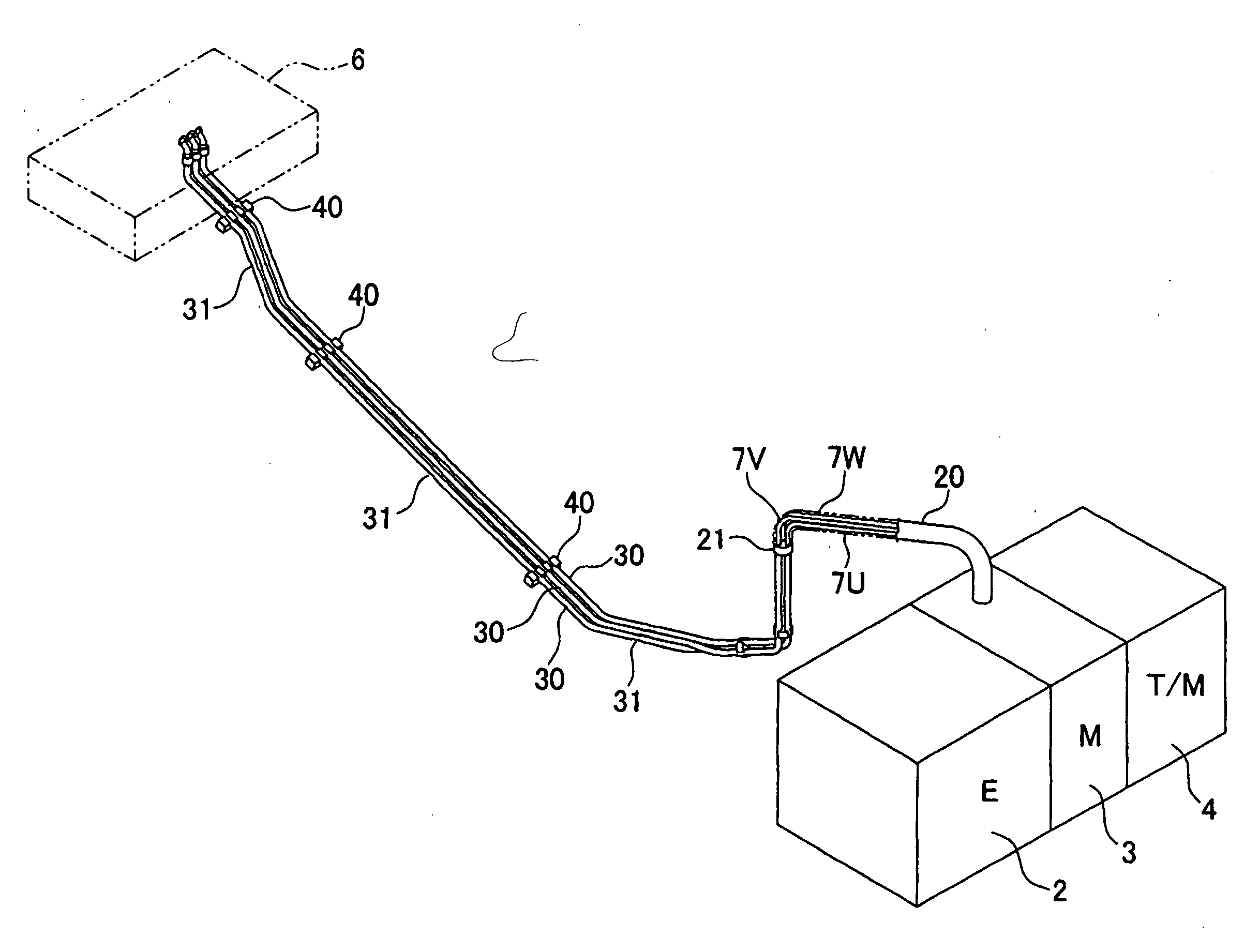
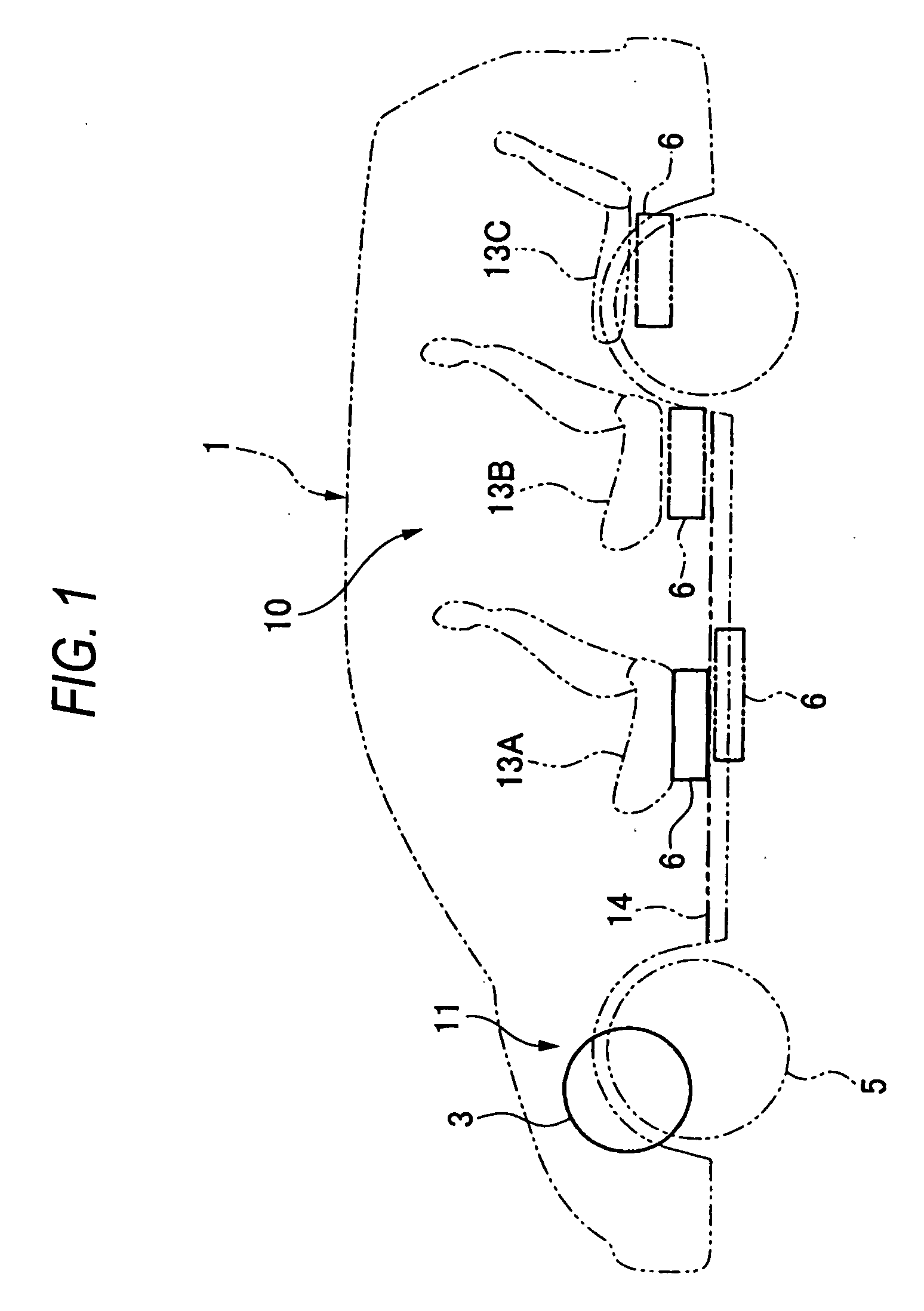
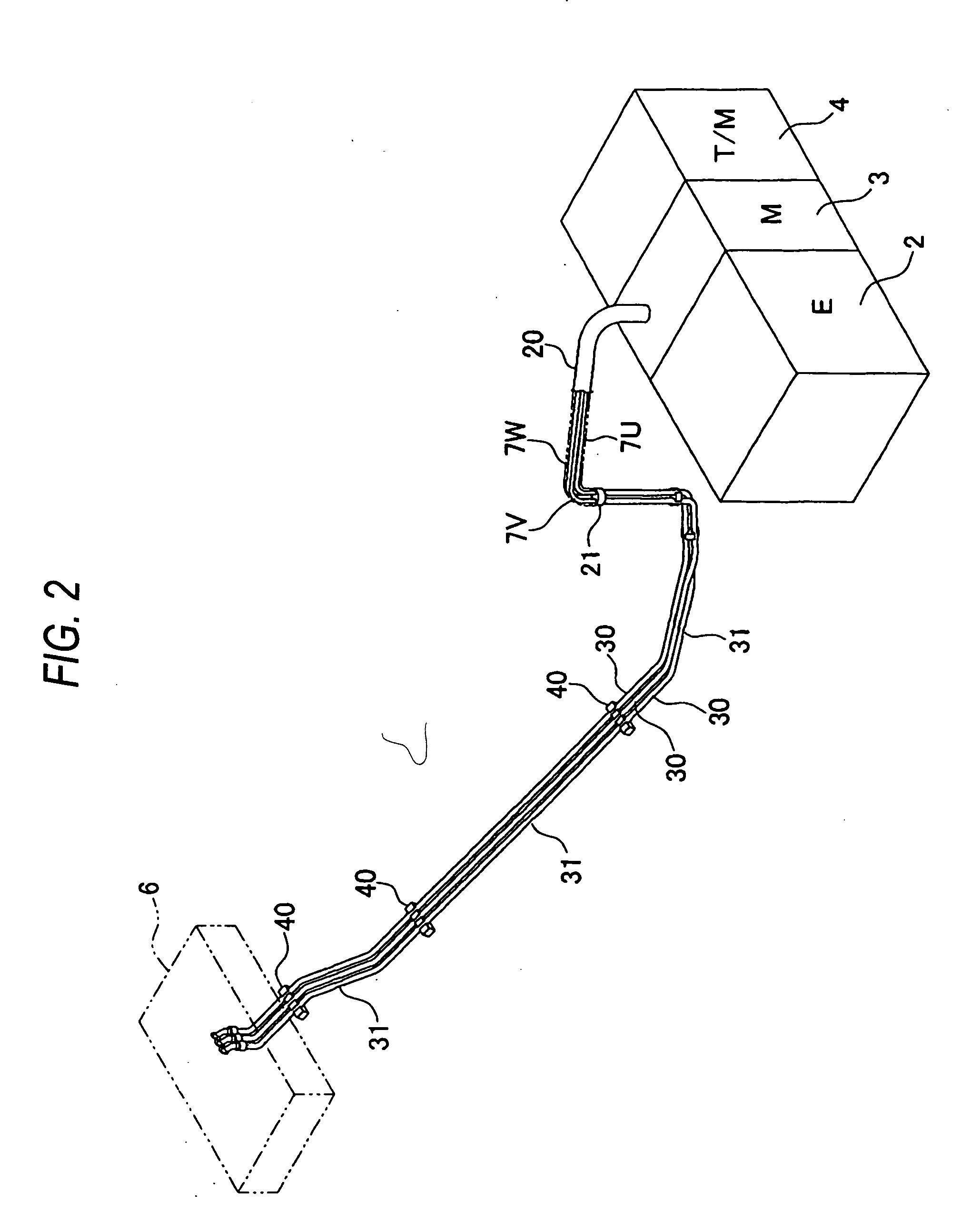
[0042]FIG. 1 is a vision through side view showing a layout of a main construction of a parallel-type hybrid vehicle 1 provided with the vehicle power cables retaining structure, and FIG. 2 is a perspective view of the power cables retaining structure.

[0043] In this hybrid vehicle 1, an engine 2 and a motor / generator 3, which are sources of power, and an automatic transmission 4 are connected directly in series. The motor / generator 3 is a three-phase DC brushless motor, and the traction of the engine 2 and the motor / generator 3 is transmitted to front wheels 5, which are driving wheels, via the automatic transmission 4. In addition, in decelerating the hybrid vehicle 1, when the traction is transmitted from the front wheels 5, which are the driving wheels, to the motor / generator 3, the motor / generator 3 fun...

second embodiment

[0069] (Second Embodiment)

[0070] Next, a second embodiment of a vehicle power cables retaining structure according to the invention will be described. The vehicle power cables retaining structure according to the second embodiment differs from that according to the first embodiment only in that the gap 32 formed between the protection pipe 30 and the high-tension cable 7 is used as a cooling passageway so that cooling air (a refrigerant) is allowed to pass through the gap 32.

[0071] Thus, when cooling air is passed through the gap 32, since not only can the high-tension cable 7 be cooled but also the protection pipe 30 can be cooled, a heat damage caused from the outside a can be prevented in an ensured fashion. In addition, the high-tension cable 7 can be maintained at a predetermined temperature or lower by adjusting the flow rate and temperature of the cooling air.

[0072] In addition, in a case where the gap 32 is used as the cooling passageway, since the cooling passageway is cl...


PUM


Abstract

High-tension cables 7U, 7V, 7W connect an inverter 6 disposed outside an engine compartment with a motor/generator 3 disposed in the engine compartment, the high-tension cables 7U, 7V, 7W are individually passed through metallic protection pipes 30 under a floor of a vehicle, the protection pipes 30 are supported from an underside of the floor, and the high-tension cables 7U, 7V, 7W are passed through a protection tube 20 over a predetermined distance from the motor/generator 3 in the engine compartment.

Description

BACKGROUND OF THE INVENTION [0001] The present invention relates to a vehicle power cables retaining structure. [0002] A power cable for supplying power from a battery to a driving motor in an electric vehicle has relatively thick in diameter and is hence relatively heavy in weight. [0003] Due to this, conventionally, as is disclosed in Patent Literature No, 1, for example, a plurality of power cables are fixed onto a floor, and the power cables so fixed are then surrounded all together by a protection cover which is formed by bending a plate material. [0004] [Patent Literature No. 1][0005] JP-A-5-207610 [0006] However, in the event that the plurality of power cables are surrounded collectively by the protection cover in the conventional fashion, a large useless space is created within the protection cover, and this leaves a problem to be solved from a viewpoint of effective use of a space above the floor. [0007] In addition, a route along which the power cables are laid out is not ...

Claims


Application Information

Patent Timeline
Patent Type & Authority Applications(United States)
IPC IPC(8): B60K6/22B60R16/02F16L9/02H02G3/04H02G3/30H02G3/38
CPCB60K6/48Y02T10/6221B60R16/0215Y02T10/62
Inventor YAMAGUCHI, HIROOTAKEDOMI, HARUMISATO, HIROMITSUKITAMI, YASUO
Owner HONDA MOTOR CO LTD
Why Eureka
Try Eureka