Toolless mounting system and method for an adjustable scalable rack power system

a rack power system and adjustable technology, applied in the direction of insulated conductors, cables, instruments, etc., can solve the problems of rats' nests, difficult, if not impossible, to locate particular cables beneath the raised floor, and high cost of raised flooring

Inactive Publication Date: 2006-01-31
AMERICA POWER CONVERSION CORP
View PDF41 Cites 97 Cited by
  • Summary
  • Abstract
  • Description
  • Claims
  • Application Information

AI Technical Summary

Problems solved by technology

There are several drawbacks with the traditional design of data centers.
First, raised flooring is expensive and cannot be easily accommodated in some facilities, such as those that do not have high ceilings.
Second, the routing of cables under raised floors often creates “rats' nests” and it often becomes difficult, if not impossible, to locate particular cables beneath a raised floor.
Further, when it is desired to add new equipment to a data center having a raised floor, it is often difficult to pull cables past existing cables under the floor, and the build up of cables beneath a floor often prevents cooling air from flowing beneath the floor to electronic equipment racks.
In addition, in many locations, building codes require that expensive metal clad cabling be used for power cables that are located beneath raised floors.
Cable ladders are somewhat difficult to install, and like raised floors, cannot be readily accommodated in facilities that do not have high ceilings.
If it later becomes necessary to add new equipment to the data center or to move equipment, the location of the ladders may not be in close proximity to equipment racks, requiring long runs of cables to racks.
Further, cable ladders and runs of cables from the ladders to equipment racks are typically fully in view and often cause a data center to appear to be overcrowded and / or cluttered.
Furthermore, installation of cable ladders can be complicated and requires a great deal of planning and installation labor.
Another drawback in the design of traditional data centers involves the difficulty in selecting the size of a UPS for the facility.
Often when these data centers are initially designed, the final power requirements for the facility are not known, and it is often not for some time, if ever, that a facility becomes fully occupied.
If the UPS is selected for full capacity, and the facility is operated at substantially below full capacity for some time, then the overhead costs of the facility may become undesirably high due to the cost of the UPS.
Further, there are power losses associated with a UPS.
If a UPS is operated at substantially below full capacity, then these losses may become significant when compared with the total power consumption of the facility.
If a UPS for a facility is selected for less than full capacity, then it may have to be replaced, at considerable cost, when the usage of the facility increases.
One problem with this approach is that installation of the UPS along with the wiring to racks often requires an electrician.
These power distribution units are often bulky items that do not fit well within data centers, and / or may require placement near a wall on which a circuit breaker panel can be mounted.

Method used


Image

  • Toolless mounting system and method for an adjustable scalable rack power system
  • Toolless mounting system and method for an adjustable scalable rack power system
  • Toolless mounting system and method for an adjustable scalable rack power system

Examples


Embodiment Construction

[0043]Embodiments of the present invention overcome problems associated with data centers described above by providing adaptable power distribution and equipment mounting systems for computers and other electronic devices.

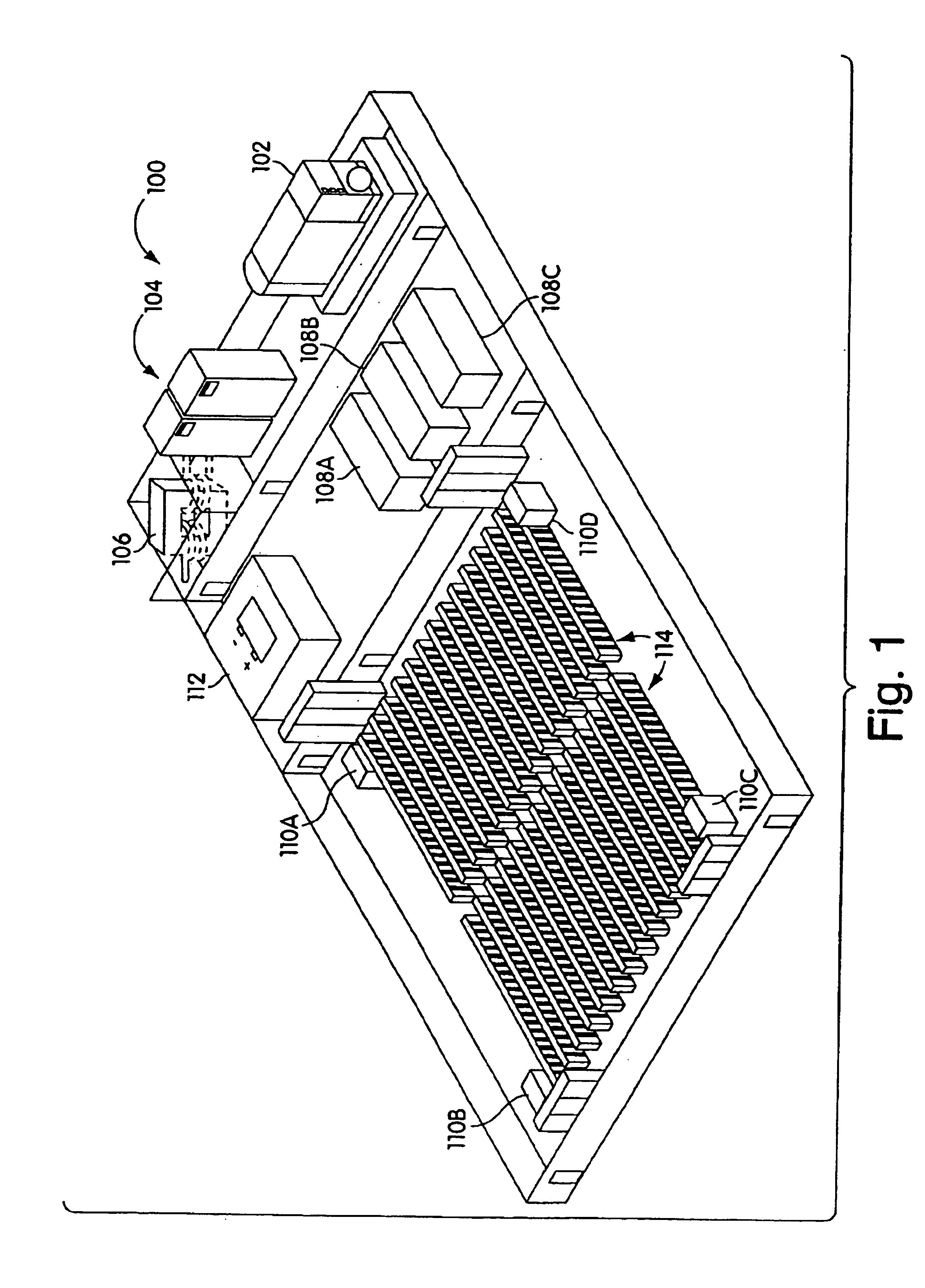
[0044]FIG. 1 shows a diagram of the layout of a typical data center 100. The data center 100 includes a generator 102, high power switchgear 104, a transformer 106, three UPSs 108A, 108B and 108C, four power distribution units (PDU) 110A, 110B, 110C and 110D, a battery or bank of batteries 112, and twenty-eight rows 114 of racks of equipment. In the data center 100, the transformer 106 is used to lower the voltage of power received from outside the facility or from the generator to a voltage level of typically 480 volts. The switchgear provides switching of the power between the generator and an outside power source and the UPSs. The UPSs in conjunction with the battery 112 provide uninterruptible power to each of the PDUs. Each PDU typically contains a transformer...


PUM


Abstract

Systems and method for installing computer equipment and power distribution equipment in facilities is provided. In one aspect, the present invention provides a power distribution rack, and uninterruptible power supply rack and a plurality of equipment racks. A plurality of power cables are run from the power distribution rack to each of the plurality of equipment racks using power cable tracks located on the roofs of the equipment racks. A plurality of data cables run between the plurality of equipment racks using data cable tracks located on the roofs of the equipment racks. The power cable tracks and data cable tracks are designed to be installed on the roofs of the equipment racks without the need for tools.

Description

[0001]The present application is a continuation-in-part of U.S. patent application Ser. No. 10 / 038,106 filed Jan. 2, 2002, entitled Adjustable Scalable Rack Power System and Method, currently pending.FIELD OF THE INVENTION[0002]The present invention relates generally to a system and method for providing power distribution and mounting facilities for electronic equipment, and more specifically to methods and apparatus for installing and powering computers and related equipment in data centers and other facilities without the need for additional hardware or tools.BACKGROUND OF THE INVENTION[0003]Centralized data centers for computer, communications and other electronic equipment have been in use for a number of years, and more recently, with the increasing use of the Internet, large scale data centers that provide hosting services for Internet Service Providers (ISPs), Application Service Providers (ASPs) and Internet content providers are become increasingly popular. Typical centrali...

Claims


Application Information

Patent Timeline
Patent Type & Authority Patents(United States)
IPC IPC(8): H02G3/04G06F1/18H05K7/14
CPCG06F1/189H05K7/1449H05K7/1497H05K7/1491H05K7/1492H05K7/1457
Inventor RASMUSSEN, NEILZIEGLER, WILLIAMFRANCIS, PETER
Owner AMERICA POWER CONVERSION CORP
Why Eureka
Try Eureka