Power converter with retractable cable system

Inactive Publication Date: 2005-06-02
IGO INC
View PDF5 Cites 113 Cited by
  • Summary
  • Abstract
  • Description
  • Claims
  • Application Information

AI Technical Summary

Benefits of technology

[0008] In a first orientation of a first embodiment of the invention, the detachable second housing is secured to the first housing to form a unitary housing. In a second orientation, the second housing is detached from the first housing such that a first end of the extended power cable may tether to the fir

Problems solved by technology

This often means that users have to carry multiple adapters for each device: one for an AC input power source, and another for a DC input power source.
Moreover, users with multiple

Method used


Image

  • Power converter with retractable cable system
  • Power converter with retractable cable system
  • Power converter with retractable cable system

Examples


first embodiment

[0046] Turning now to FIG. 5, there is shown the present invention comprising the PPH 44 shown in FIG. 4. As previously mentioned, the input DC voltage provided to the PPH 44 at input 62 is coupled to each of the output ports 46 by a voltage mux 64. This coupling of the input DC voltage to the multiple output ports 46 can be accomplished in a number of ways, such as via a simple resistive divide network, and may provide output-to-output isolation. In one implementation, the DC voltage provided at input 62 is directly provided to the output ports 46 for a subsequent down-stepping via the associated buck circuit 28. However, a lower voltage can be provided by the voltage mux 64 to each of the output ports 46 if desired. Voltage mux 64 is also seen to include an over load protection circuit generally shown at 66 which limits the amount of power that can be provided to each output port 46, such as 7 watts, to prevent overload of the PPH 44, and to prevent power hoarding at one output by...

embodiment 60

[0048] The advantages of the embodiment 60 shown in FIG. 5 include that a separate buck circuit 28 and the associated cord can be simply coupled to any of the output ports 46 and provide a programmable DC output voltage meeting ther needs of the associated remote device 72. A user having a buck circuit 28 / cord for use with the particular remote device 72 can be plugged into any of the available output ports 46 of the PPH 44. The DC voltage is stepped down by buck circuit 28 external to the housing of PPH 44. This solution is low cost and a simple design.

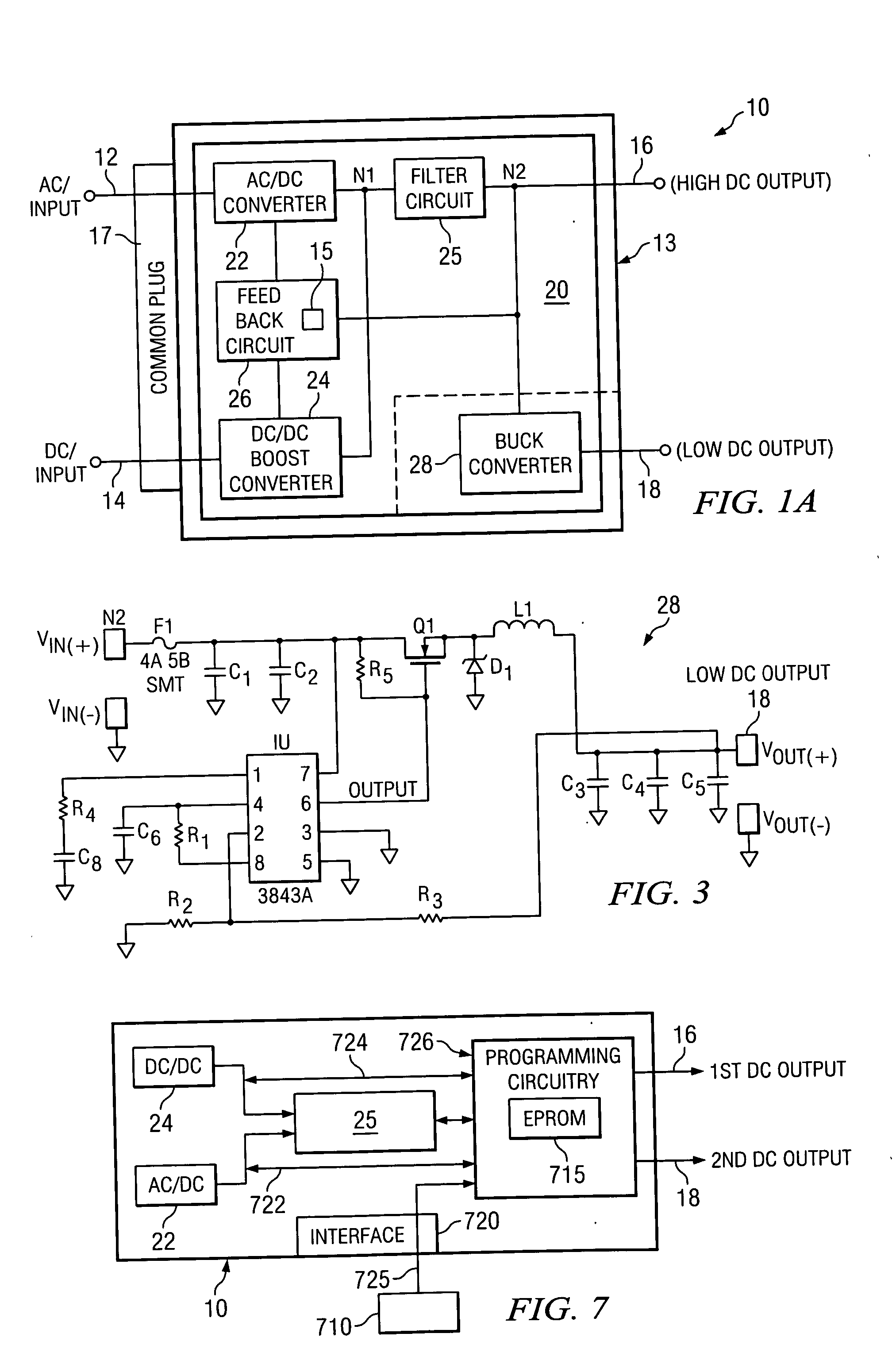
[0049] Turning now to FIG. 6, there is shown at 70 another preferred embodiment of the present invention whereby a plurality of buck circuits 28 are provided within the PPH 44 to provide a programmable output DC voltage to the respective output port 46. Each buck circuit 28, as shown in FIG. 3, has an associated programming resister R1 which may be selectively removable from the PPH 44 to selectively establish the output DC voltage p...

embodiment 70

[0050] Advantages of this embodiment 70 include that the buck circuits 28 are enclosed in the PPH 44, where each buck circuit 28 itself may be programmable using the associated programming resistor R1. In this arrangement, care must be taken that the remote device 72 is coupled to an output port having a desirable output voltage. Thus, the keys provide indicia of the output voltage being provided. The voltage mux 64 simply provides the input voltage at input 62 to each of the buck circuits 28, which may step down (or step up) the voltage thereat. Voltage mux 64 includes the overload protection circuit 66, the associated LED's 68, and the hub main fuse 69 as shown.

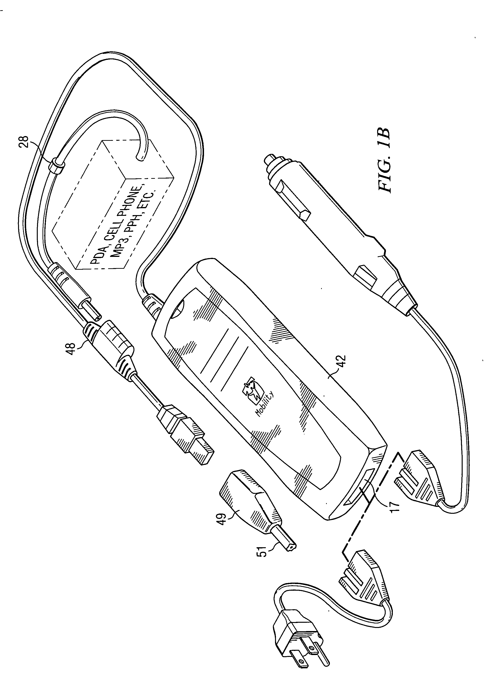
[0051] Both embodiments 60 and 70 provide a DC peripheral power hub adapted to power a plurality of unique remote devices 72 from a single unit 44, such remote devices including a cell phone, PDA, MP3 player, etc. This peripheral power hub 44 may be an accessory to power converter 42, or, a stand alone device receiving powe...


PUM


Abstract

A modular power converter including a first housing enclosing a converter circuit, and a selectively detachable second housing enclosing a retractable power cable. In a first orientation the detachable second housing is secured to the first housing to form a unitary housing. In a second orientation, the second housing is detached from the first housing such that a first end of the extended power cable may tether to the first housing output a selectable distance therefrom. The cable also has a second end extendable from the second housing a predetermined distance. This modular power converter forms a single compact device when the power cable is not extended from the second housing.

Description

CROSS REFERENCE TO RELATED APPLICATIONS [0001] This application claims priority from U.S. Provisional Patent application Ser. No. 60 / 525,257 entitled Retractable Cable System for Power Converter filed Nov. 26, 2003, and is a continuation-in-part of U.S. patent application Ser. No. 10 / 623,060 filed Jul. 18, 2003, which is a continuation-in-part of U.S. patent application Ser. No. 10 / 384,263 filed Mar. 7, 2003, which is a continuation-in-part of U.S. Ser. No. 10 / 225,933 filed Aug. 22, 2002, which is a continuation-in-part of U.S. patent application Ser. No. 10 / 159,910 filed May 31, 2002, which is a continuation-in-part of U.S. patent application Ser. No. 10 / 005,961 filed Dec. 3, 2001, and which U.S. patent application Ser. No. 10 / 623,060 is also is a continuation-in-part of U.S. patent application Ser. No. 10 / 072,074 filed Feb. 8, 2002, the teachings of which are incorporated herein by reference.TECHNICAL FIELD OF THE INVENTION [0002] The present invention generally relates to the fie...

Claims


Application Information

Patent Timeline
IPC IPC(8): G06F1/26H02J9/06H02M1/10H02M3/335
CPCG06F1/263H02M3/33561H02M1/10H02J9/061
Inventor WILSON, JOHN
Owner IGO INC
Why Eureka
Try Eureka