Re-writeable optical element and a display, reflector and backlight incorporating the same

a technology of optical elements and reflectors, applied in the field of rewriteable optical elements, can solve the problems of increasing costs, occupying a lot of space, and requiring a separate display screen for each player, and achieve the effect of reducing power consumption

Inactive Publication Date: 2007-12-13
SHARP KK
View PDF25 Cites 103 Cited by
  • Summary
  • Abstract
  • Description
  • Claims
  • Application Information

AI Technical Summary

Benefits of technology

[0044]A first aspect of the present invention provides an optical element comprising: a material thermally switchable between a first stable state and a second stable state different from the first stable state; and a switching mechanism for switching at least a selected area of the material between the first stable state and the second stable state thereby to change the transmissivity of one or more selected areas of the optical element, wherein the material is bistable or multistable, and the first and second stable states are its two bistable states (in the case of a bistable material) or are two of its stable states (in the case of a multistable material). Use of a bistable or multistable material means that a heat pulse is required to be applied only when it is desired to switch the material, thereby reducing power consumption.
[0049]Another example, still concerning a motor vehicle, would be to cover the wing mirrors and / or the rear view mirror by an optical element of the invention, to allow the driver the dim the brightness of the reflected image, for example when bright headlights of a car behind are reflected in the mirror. This would reduce the inconvenience of such a case and also reduce the chance of an accident as a result of the driver being dazzled.
[0065]Switching a selected area of the material from the first stable state to the second stable state may reduce the transmissivity of a corresponding area of the optical element. It may reduce the transmissivity of a corresponding area of the optical element to substantially zero.

Problems solved by technology

These conflicting needs could be satisfied by providing two separate display devices, but this would take up extra space and would increase the cost.
Furthermore, if two separate displays were used in this example it would be possible for the driver to see the passenger's display if the driver moved his or her head, which would be distracting for the driver.
However, providing a separate display screen for each player takes up a lot of space and is costly, and is not practical for portable games.
However, the two images displayed on an autostereoscopic display are the left-eye and right-eye images of a stereoscopic image pair, and so are not independent from one another.
However, light travelling at large angles to the plane of the opaque layers is incident on one of the opaque layers and is absorbed.
However none of the prior art light control films enables the privacy function to be switched off to allow viewing from a wide range of angles.
This method has the disadvantage that it contains moving parts which may fail or be damaged in use, and which add bulk to the display.
They have the disadvantage that the light control film always absorbs a significant fraction of the light incident upon it, whether the display is in public mode or private mode.
The display is therefore inherently inefficient in its use of light.
Another disadvantage of these devices relates to their power consumption.
This is a disadvantage for mobile devices which are used for most of the time in the public mode and which have limited battery power.
One significant disadvantage of this device is the difficulty and expense of manufacturing liquid crystal cells with an appropriate shape.
A second disadvantage is that, in the private mode, a ray of light may enter at an angle such that it passes first through the transparent material and then through part of a liquid crystal cell.
Such a ray will not be completely absorbed by the liquid crystal cell and this may reduce the privacy of the device.
However, when the display is viewed from a non-central position, pixels that are supplied with non-inverted image data are viewed through the retarder elements of the PML, and the image is corrupted.

Method used


Image

  • Re-writeable optical element and a display, reflector and backlight incorporating the same
  • Re-writeable optical element and a display, reflector and backlight incorporating the same
  • Re-writeable optical element and a display, reflector and backlight incorporating the same

Examples


Embodiment Construction

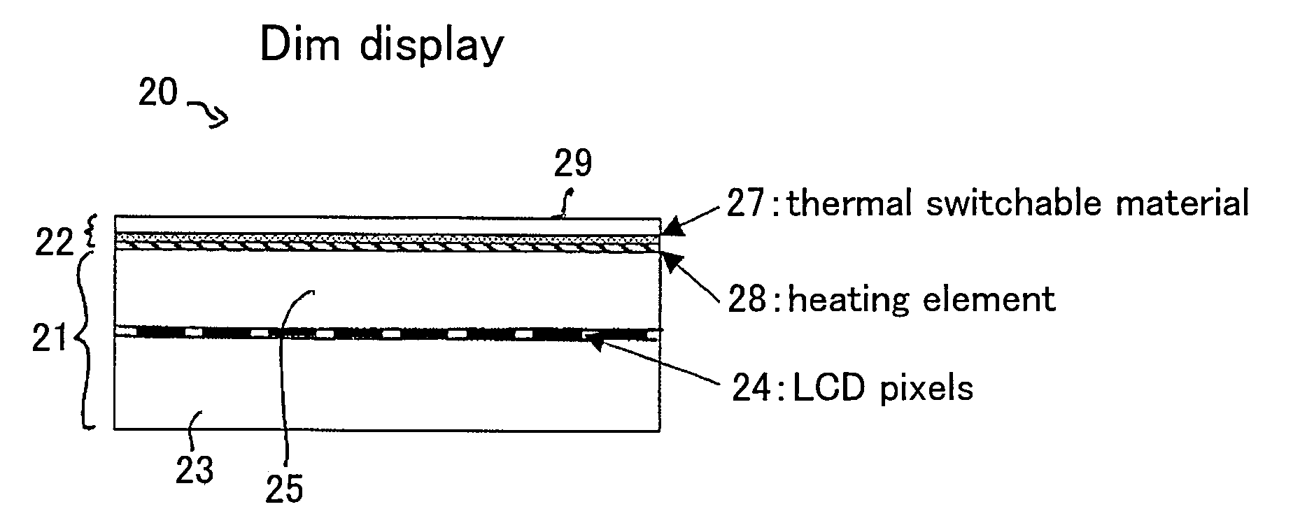
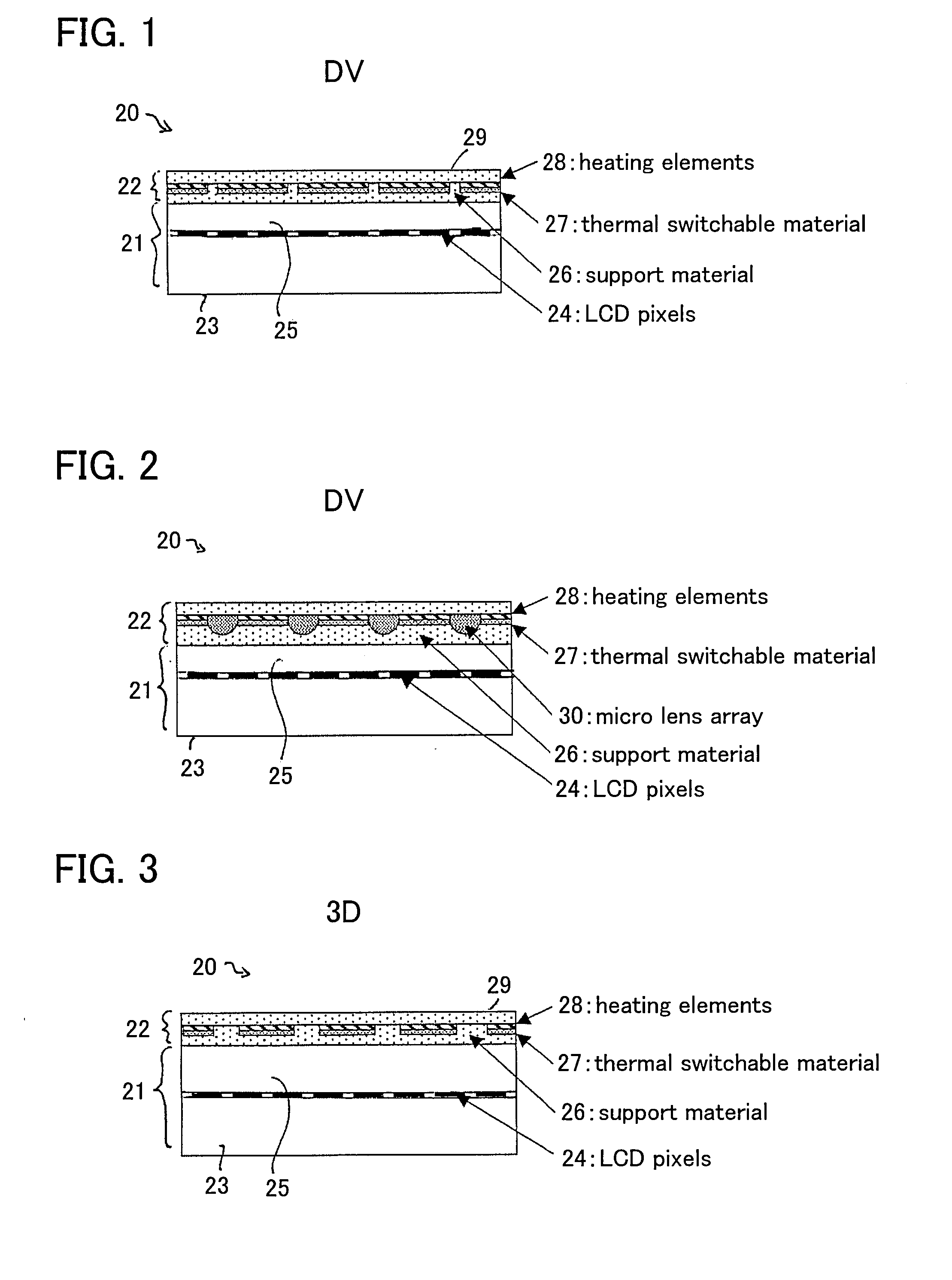
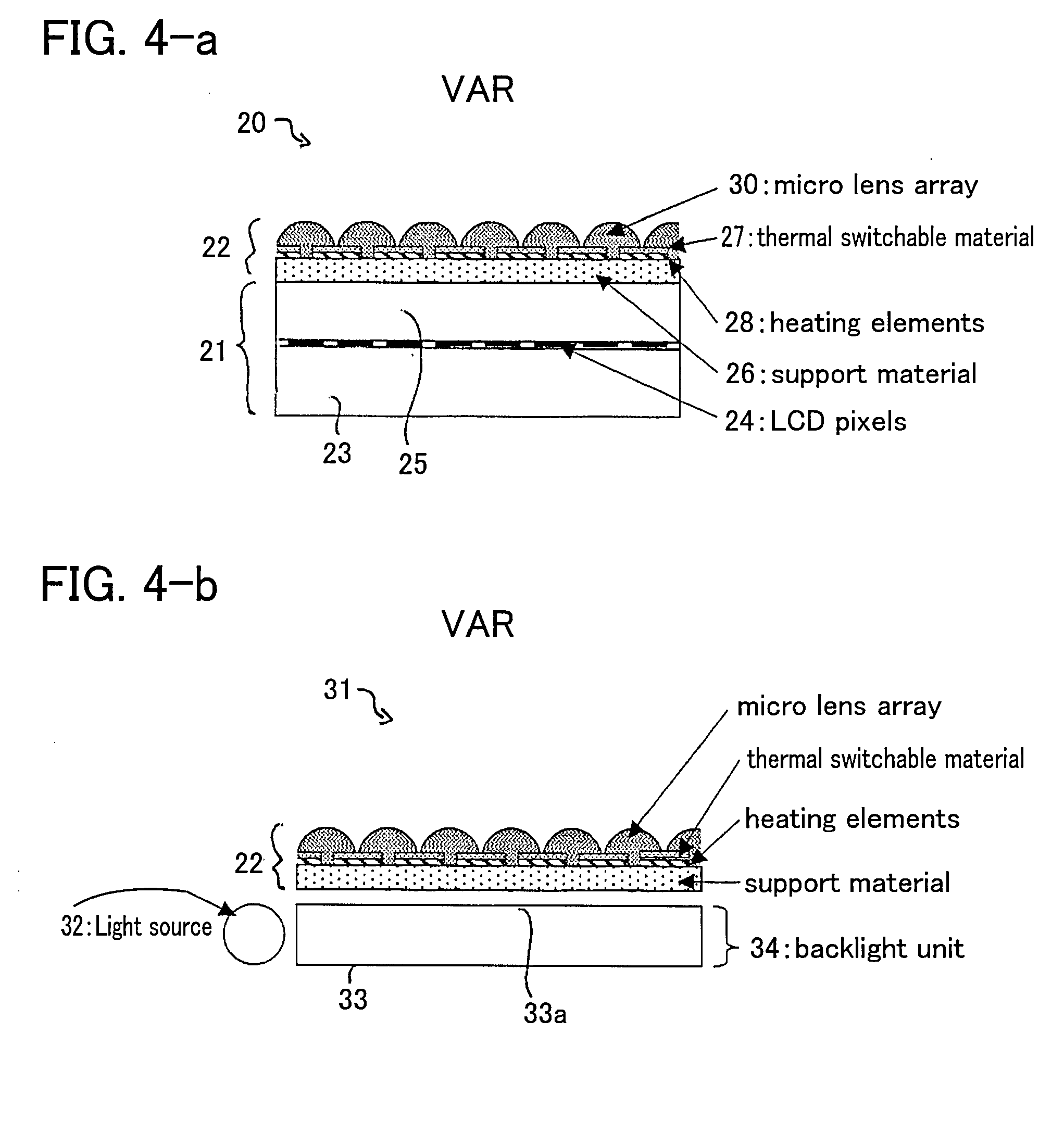
[0105]FIG. 1 is a cross-sectional view through a display 20 according to one embodiment of the present invention. The display comprises an image display panel 21 and an optical element 22 arranged in an optical path through the display panel 21. The image display panel 21 may be any suitable or conventional image display panel, and is represented in FIG. 1 as an image display layer 24, for example a pixelated liquid crystal layer, disposed between first and second transparent substrates 23, 25. The nature of the image display panel 21 is however not material to the present invention, and the image display panel will not be described further.

[0106]The optical element 22 contains a material 27 that is thermally switchable between at least a first stable state and a second, different stable state. The element also contains switching means for switching the material from one stable state to another, and in the embodiment of FIG. 1 the switching means are arranged to, in use, heat the th...


PUM


Abstract

An optical element (22) comprises a material (27) thermally switchable between a first stable state and a second stable state different from the first state and a switching mechanism (28a-28c) for switching one or more selected areas of the material (27) between the first state and the second state thereby to change the transmissivity of one or more selected areas of the optical element (22). The optical element may be placed in an optical path through another component such as, for example, a display (21), reflector or backlight, such that the optical element may be controlled to change the optical properties of the component. The properties that may be changed include, but are not limited to, the display mode of a display (21), viewing angle range, brightness / luminance, and colour. For example, if the element is substantially non-transmissive for one state of the thermally switchable material, the thermally switchable material may be arranged to provide a parallax barrier, in one state. Thus a display (21) may be switched between a directional display mode, for example a 3D-mode or multi-view display mode, and a conventional 2-D display mode by putting the thermally switchable material into its appropriate state—when the thermally switchable material is put into the non-transmissive state the parallax barrier is enabled, and when the thermally switchable is put into another state the parallax barrier is disabled.

Description

[0001]This Nonprovisional application claims priority under 35 U.S.C. § 119(a) on Patent Application No. 0611655.2 filed in Great Britain on Jun. 13, 2006, the entire contents of which are hereby incorporated by reference.FIELD OF THE INVENTION[0002]The present invention relates to a re-writeable optical element which may be re-written so as to change the transmissivity of part, or all, of the element. The optical element may be placed in the optical path through another component, such as for example a display, such that the optical element may be controlled to change the optical properties of the component. Such an optical element may be used, for example, with a display to define a switchable parallax barrier so that the display can be switched between a 2-D display mode and an autostereoscopic display mode or a dual view display mode. The invention also relates to a display, reflector or backlight incorporating such an optical element.BACKGROUND OF THE INVENTION[0003]For many ye...

Claims


Application Information

Patent Timeline
Patent Type & Authority Applications(United States)
IPC IPC(8): G02B27/26G02B30/25
CPCG02F1/1335G02F1/0147G02B30/00
Inventor LESAGE, ETIENNEMATHER, JONATHAN
Owner SHARP KK
Why Eureka
Try Eureka