Soil compaction apparatus

a soil compaction and apparatus technology, applied in the direction of soil preservation, roads, roads, etc., can solve problems such as non-uniform compaction over the si

Inactive Publication Date: 2000-05-23
COMPACTION TECH SOIL
View PDF7 Cites 34 Cited by
  • Summary
  • Abstract
  • Description
  • Claims
  • Application Information

AI Technical Summary

Problems solved by technology

However a problem which is encountered during compaction of a site is that of non-uniformity of soil and other conditions over the site, leading to non-uniform compaction over the site.

Method used


Image

  • Soil compaction apparatus
  • Soil compaction apparatus
  • Soil compaction apparatus

Examples


Embodiment Construction

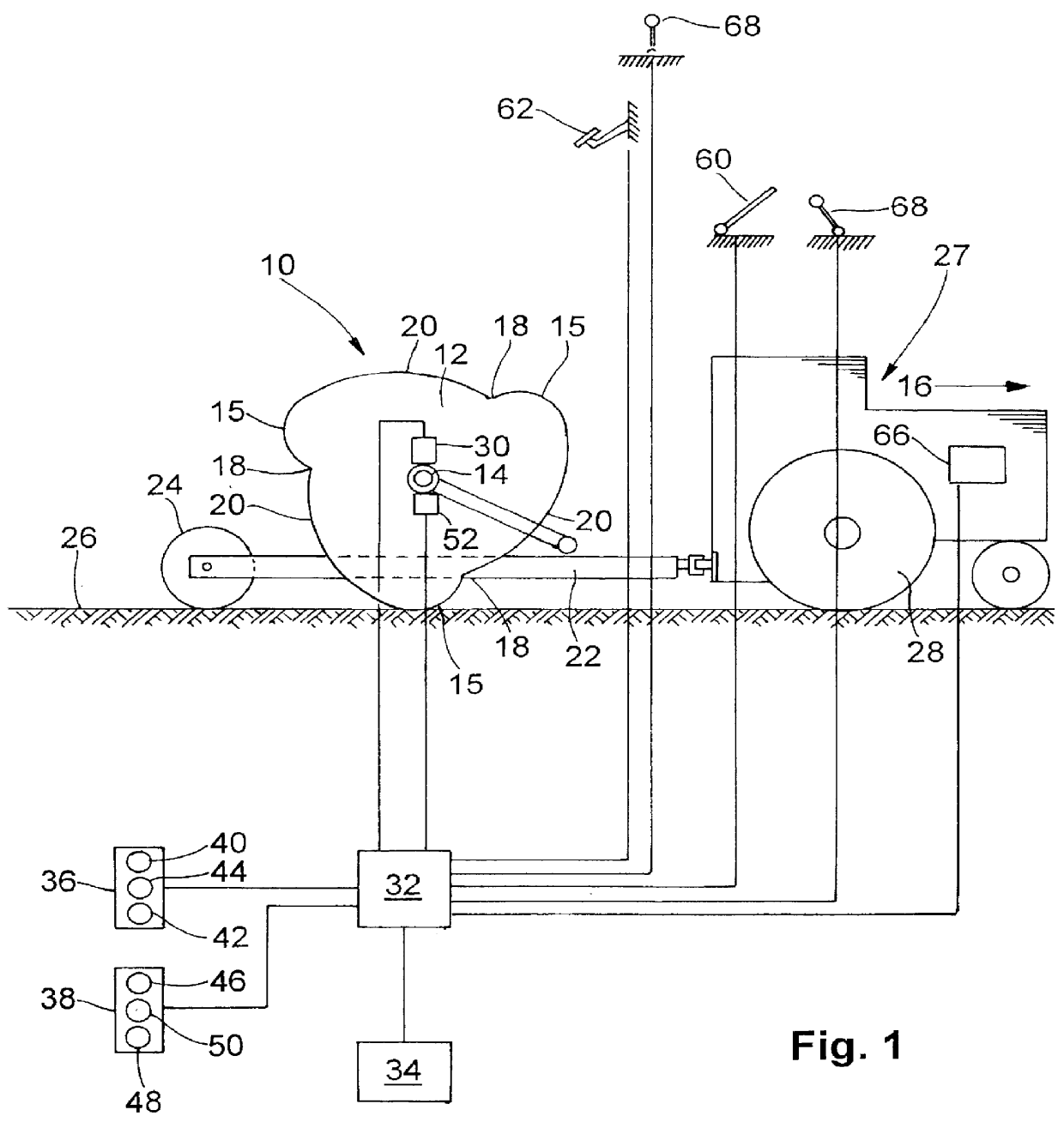
In the diagrammatic illustration of FIG. 1, the numeral 10 generally indicates an impact compactor according to the invention. The impact compactor 10 is largely conventional and may be conventional and may be taken to be a dual mass impact compactor of the type described in U.S. Pat. No. 4,422,795 to Berrange. Only one of the compactor masses, indicated by the numeral 12, is visible in the drawing, and the numeral 14 indicates the axle which connects the masses to one another and causes them to rotate in unison.

As illustrated, each compactor mass 12 is a three-sided mass with three salient points 15 each followed, in the direction of rotation when the impact compactor moves in the forward direction indicated by the arrow 16, by a re-entrant formation 18. Each of the re-entrant formations is followed in turn by a compacting face 20. The compactor masses 12 are carried by a chassis 22 mounted on road wheels 24, only one of which is visible. The chassis and compactor masses are towed ...


PUM


Abstract

An apparatus for monitoring soil compaction using a compaction machine which applies periodic impact blows to the soil surface. The apparatus comprising a rotatable, multi-sided compactor mass that applies periodic impact blows to the soil surface when rolled over that surface. Data related to the level of compaction of the soil surface is derived, during compaction of the soil surface, from the deceleration of the compactor mass as it impacts the soil surface. This is achieved using one or more accelerometers mounted on the impact compactor.

Description

BACKGROUND TO THE INVENTIONTHIS invention relates to the monitoring of soil compaction using a compaction machine which applies periodic impact blows to the soil surface.In one application of the invention, it is applicable to the monitoring of soil compaction by an impact compactor. The term "impact compactor", as used initially in U.S. Pat. No. 2,909,106, refers to a soil compaction machine which incorporates an out-of-round mass which produces a series of impact blows to the soil surface when towed or otherwise driven over that surface. The compactor mass of an impact compactor has multiple sides defining a series of spaced apart salient points on its periphery, each salient point being followed by a compacting face. As the impact roller is towed or moved over the soil surface, it rises up on each salient point and then falls forwardly and downwardly as it passes over that point, with the result that the following compacting face applies an impact blow to the soil surface. The ac...

Claims


Application Information

Patent Timeline
Patent Type & Authority Patents(United States)
IPC IPC(8): E01C19/28E01C19/23E02D3/00E02D3/026E01C19/22
CPCE01C19/235E02D3/026E01C19/288
Inventor COOK, ERIC JOHNSTONEBERRANGE, AUBREY RALPH
Owner COMPACTION TECH SOIL
Why Eureka
Try Eureka