Boring bar

a technology of boring bar and bending rod, which is applied in the field of boring bar, can solve the problems of rigid screw joint, no vibration damping effect, and no tool construction

Inactive Publication Date: 2000-06-20
SANDVIK INTELLECTUAL PROPERTY AB
View PDF17 Cites 69 Cited by
  • Summary
  • Abstract
  • Description
  • Claims
  • Application Information

AI Technical Summary

Problems solved by technology

However, these tools are not at all constructed for vibration damping purposes, but only for simplifying the repl...

Method used


Image

  • Boring bar
  • Boring bar
  • Boring bar

Examples


Embodiment Construction

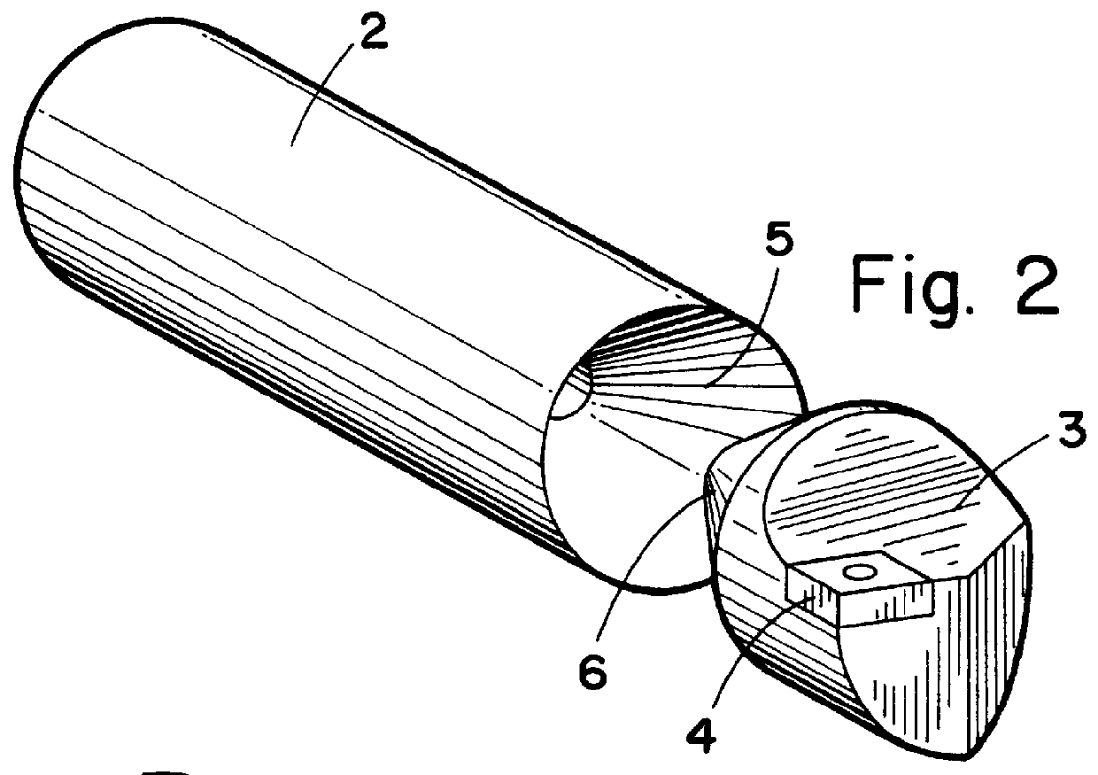
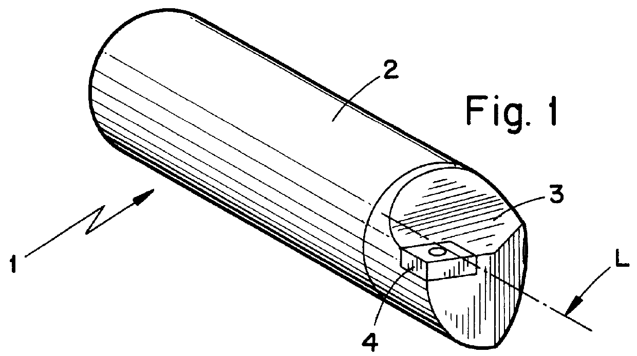
In FIG. 1 a boring bar 1 is generally shown comprising a shaft portion 2 and a bar head 3. The rear part of the shaft is introduced into a holder in a way known per se, whereafter the necessary clamping force is obtained by a screw joint or by a hydraulic bushing. The shaft portion may be formed in a number of different ways, depending on which properties are desired and is not an essential feature of the invention. On the bar head 3 is clamped a suitable cutting insert 4 formed of a hard material, such as cemented carbide. The cutting insert is fastened in its insert seat by a locking screw, a clamp or similar.

Generally, a very large amount of materials are possible both for forming both the shaft portion and the bar head, as long as they fulfil the requirements relating to strength and function, e.g., both may be produced of tool steel or spring steel, such as SS 2230. Further, in order to reduce the weight and increase the natural frequency, the bar head may also be made of a lig...


PUM

PropertyMeasurementUnit
Thicknessaaaaaaaaaa
Thicknessaaaaaaaaaa
Shapeaaaaaaaaaa

Abstract

PCT No. PCT/SE97/01232 Sec. 371 Date May 14, 1999 Sec. 102(e) Date May 14, 1999 PCT Filed Jul. 7, 1997 PCT Pub. No. WO98/01250 PCT Pub. Date Jan. 15, 1998A boring bar includes a shaft and a head which carries a cutting insert. The head includes a conical protrusion which fits in a correspondingly shaped recess of the shaft and is secured therein by an adhesive joint in order to damp vibrations.

Description

The present invention relates to a boring bar, a process for the production of a boring bar, and the use of such a boring bar for the damping of vibrations during internal turning.Turning operations can be divided into those for external turning and those for inner turning, the latter normally called internal turning. As the names indicate, external turning operations relate to turning on an external rotating surface of a workpiece, while internal turning refers to turning on an inner rotating surface. A special case of external turning is face turning.During external turning, the overhang of the tool is not influenced by the length of the workpiece since external rotating surfaces usually are exposed and freely accessible. Thus, dimensions of tool holders may be chosen so that they resist the forces or stresses that arise. However, during internal turning the choice of tool is restricted by the appearance of the workpiece, since this turning operation is usually applied in pre-dril...

Claims


Application Information

Patent Timeline
IPC IPC(8): B23B27/00B23B29/02B23B29/00
CPCB23B27/007B23B29/022Y10T408/78Y10T407/2272Y10T407/22Y10T407/26Y10T407/27
Inventor HEDBERG, ANNATJERNSTROM, ERIC
Owner SANDVIK INTELLECTUAL PROPERTY AB
Why Eureka
Try Eureka