Method and device for fixing spondylolisthesis posteriorly

a technology for spondylolisthesis and posterior fixation, which is applied in the field of method and apparatus for fixing spondylolisthesis, can solve the problems of multiple steps, requiring the removal of the disk, and patents with disadvantages

Inactive Publication Date: 2000-07-11
SPINEOLOGY
View PDF9 Cites 251 Cited by
  • Summary
  • Abstract
  • Description
  • Claims
  • Application Information

AI Technical Summary

Problems solved by technology

That patent has a disadvantage in requiring removal of the disk and having multiple steps, that is,

Method used


Image

  • Method and device for fixing spondylolisthesis posteriorly
  • Method and device for fixing spondylolisthesis posteriorly
  • Method and device for fixing spondylolisthesis posteriorly

Examples


Embodiment Construction

is hereafter described with specific reference being made to the drawings in which:

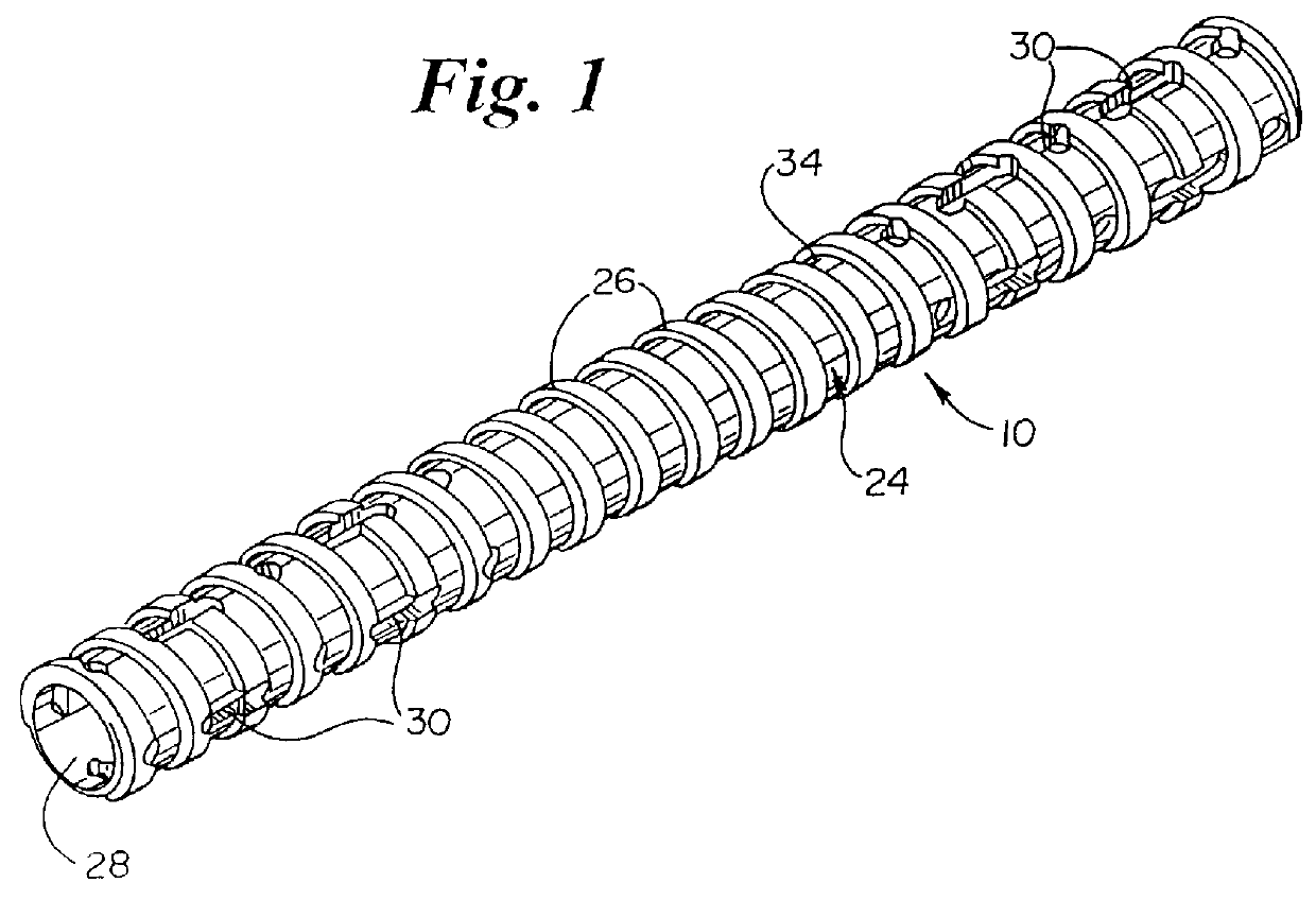
FIG. 1 is a perspective view of the apparatus of the invention;

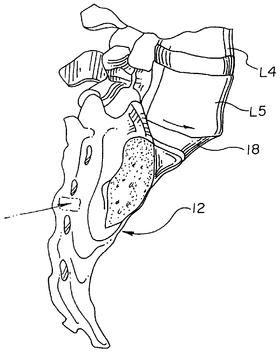
FIG. 2 is a side view of the sacrum and L4 and L5 vertebrae;

FIG. 3 is a posterior view of the vertebrae of FIG. 2;

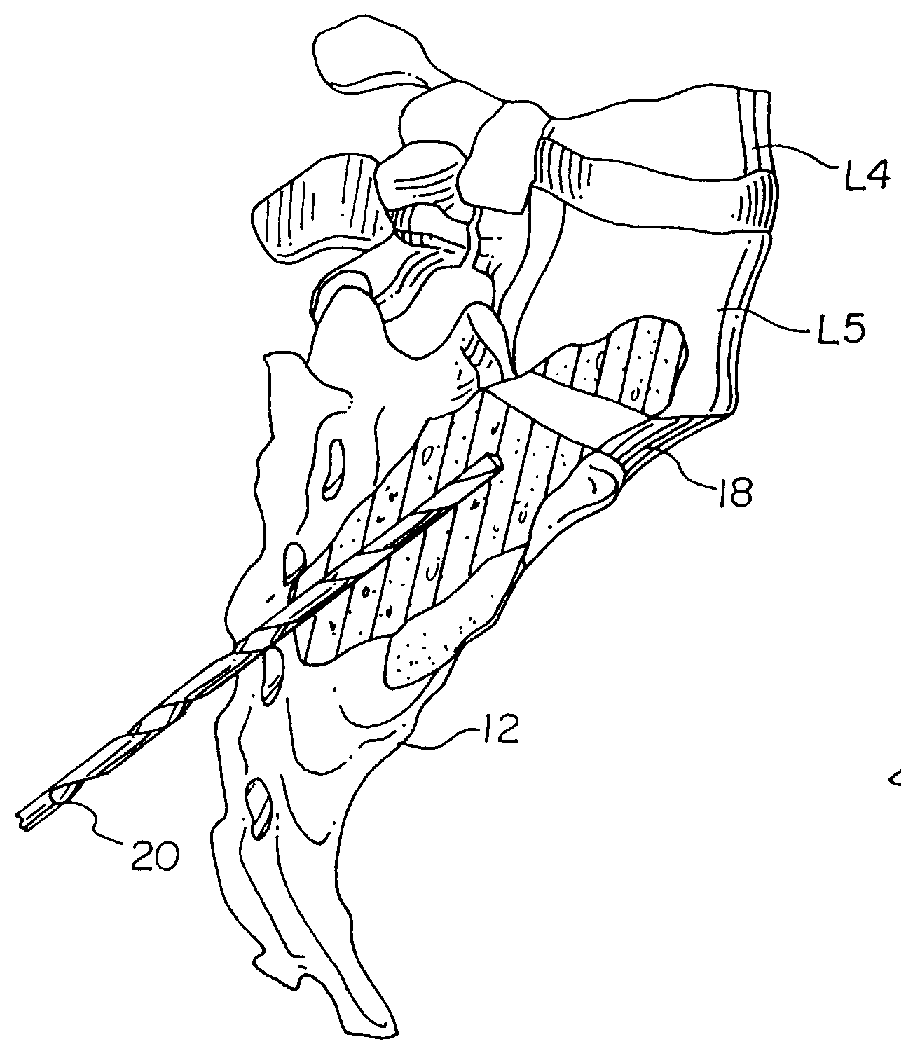
FIG. 4 is a side view of the vertebrae showing a drill hole being formed through the sacrum into the L5 vertebra;

FIG. 5 is a side view showing the apparatus of the invention being threaded into the drill hole of FIG. 4;

FIG. 6 is a side view showing the apparatus being inserted into a pre-threaded opening; and

FIG. 7 is a side view showing insertion of bone in growth material into the bore of the apparatus and into the disk space.

With reference to the Figures, it will be seen that a typical misalignment, or spondylolisthesis of vertebrae occurs in between the sacrum 12 and the L5 and L4 vertebrae. Typically, the L5 vertebra is pushed anteriorly from the desired position. As shown in FIGS. 2 and 4, a drill 20 is positioned and dri...


PUM


Abstract

A method and apparatus for fixation of spondylolisthesis includes an elongated, threaded, hollow shaft which is threaded into a bore hole correctly formed between correctly aligned vertebrae posteriorly. The shaft includes a plurality of openings therethrough in the distal and proximal ends to allow bone and fibrous through growth to stabilize the vertebrae to decrease associated pain.

Description

1. Field of the InventionThis invention relates to a method and apparatus for fixing of spondylolisthesis, e.g., misalignment of the vertebrae comprising the spinal column. More specifically, the present invention relates to an apparatus which is screwed into a drill hole through one vertebra into the adjacent vertebra and a method utilizing that apparatus.2. Description of the Related ArtTreatments for conditions involving subluxation of one vertebrae upon another, resulting in misalignment of the spinal column, involve the use of screws which extend through a plate and which are tightened to draw the misaligned vertebrae back into alignment. U.S. Pat. No. 5,531,747 to Ray (hereinafter "Ray") is an example of a plate and screw system for treating spondylolisthesis. Other approaches include insertion of an implant into the disk space between misaligned vertebrae such as shown in U.S. Pat. No. 5,601,556 to Pisharodi (hereinafter "Pisharodi"). The Ray approach has its limitations as d...

Claims


Application Information

Patent Timeline
IPC IPC(8): A61B17/68A61B17/70A61B17/86
CPCA61B17/70A61B17/864
Inventor KUSLICH, STEPHEN D.AHERN, JAMES
Owner SPINEOLOGY
Why Eureka
Try Eureka