Ball screw unit

Inactive Publication Date: 2000-07-18
THK CO LTD
View PDF10 Cites 63 Cited by
  • Summary
  • Abstract
  • Description
  • Claims
  • Application Information

AI Technical Summary

Problems solved by technology

Therefore, in the cases of the above-described conventional ball screw units, when each of the balls rolling in the load zone is picked up into the no-load zone or the balls in the no-load zone are fed to the load zone, the presence of the tongue (g) for changing the progressing direction of the rolling balls is indispensable so that the smooth circulation of the balls is impaired and as a result, the uniform and stabilized rotation of the ball screw unit is impaired, the working life of the unit is shortened or noises generate.
However, in the case of such ball screw unit, the belt-like retainer(i) assembled into the ball circulation path(h) is inevitably twisted and bent and it is necessary to absorb such twisting and bending of the retainer (i) within the ball circulation path(h) so that although the idea of "providing a ball screw unit having an excellent operation characteristic by preventing the adjoining balls from coming into contact with e

Method used


Image

  • Ball screw unit
  • Ball screw unit
  • Ball screw unit

Examples


first embodiment

[ Tube type ball screw unit]

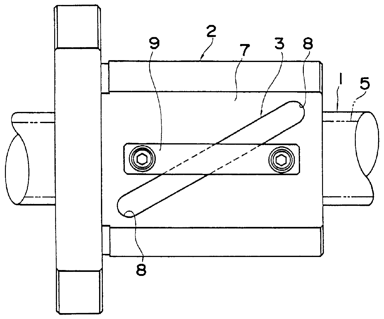
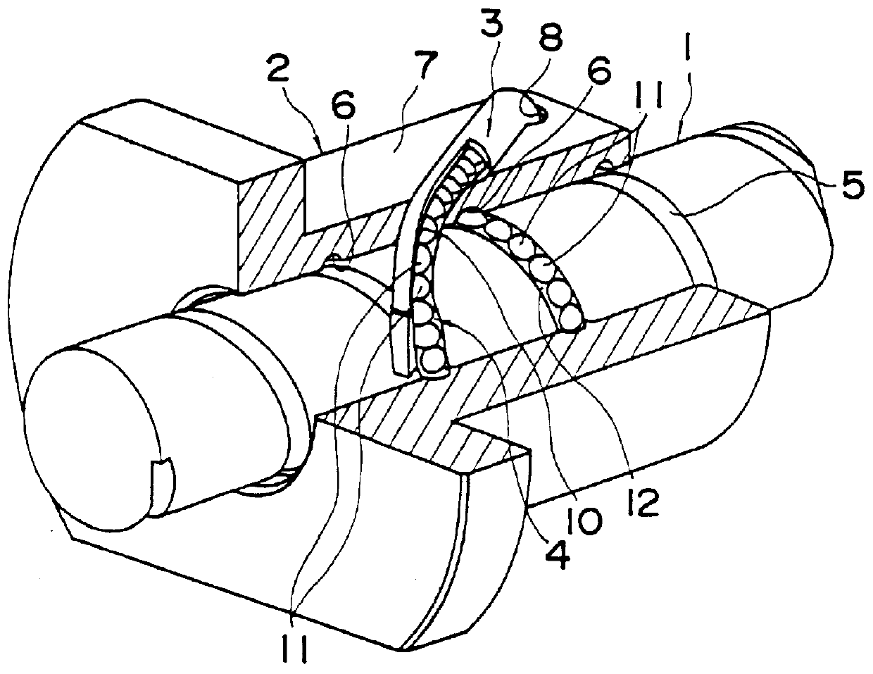
A tube type ball screw unit according to the present invention is shown in FIGS. 1 and 2. This ball screw unit basically comprises a screw 1 provided on the outer peripheral surface thereof with a helical ball rolling groove 5, a cylindrical nut 2 provided with a central through hole for receiving the screw 1, a helical load rolling groove 6 formed on the inner peripheral surface thereof so as to lie opposite to the ball rolling groove 5 of the screw 1, a flat mounting surface 7 on the outer peripheral surface thereof and a pair of fitting holes 8 drilled at positions on a diagonal line of the mounting surface 7 so as to extend from the mounting surface 7 toward a starting end and a terminating end of the load rolling groove 6, respectively, a ball circulating tubular body 3 mounted on the mounting surface 7 of the nut 2 by means of a fixture 9 and having a no-load ball path 10 which establishes communication between the starting end and the terminating e...

second embodiment

[ A tube type ball screw unit]

FIGS. 20 through 22 concern a tube type ball screw unit as in the case of the first embodiment but unlike the first embodiment, the whole of the ball circulating tubular body 3 is in the shape of a substantially U-shaped tube having both ends 3a thereof fixedly fitted into a pair of fitting holes 8 formed in the nut 2. Further, the ball circulating tubular body 3 is provided with guide holes 10a at both ends 3a thereof as in the case of the tubular piece 15 of the first embodiment and at the central portion 3b thereof there is provided a communication hole 10b as in the case of the tubular body 16 of the first embodiment so that these guide holes 10a and the communication hole 10b form themselves a no-load ball path 10 for forming a no-loaded zone of the endless track for the balls 11.

In this second embodiment, the guide holes 10a which are respectively formed at both ends 3a of the tubular body 3 form themselves guide zones each extending tangentially ...

third embodiment

[ Side cover type ball screw unit]

FIGS. 23 and 24 show a side cover type ball screw unit according to the present invention. This ball screw unit basically comprises a screw 101 having two helical ball rolling grooves 105 on the outer peripheral surface thereof, a nut 102 in the form of a cylinder having a through hole at the center thereof for receiving the screw 101, two helical load rolling grooves 106 on the inner peripheral surface thereof in opposite relationship with the two helical ball rolling grooves 105 of the screw 101 and two ball return holes (no load ball paths) 107 formed at opposing positions at an outer peripheral solid portion thereof and adapted to circulate balls 109 from one end of the load rolling groove 106 to the other end thereof along the axial direction; a pair of side covers 103 mounted on the both ends of the nut 102 and having two change direction paths 108 for establishing communication between the load rolling groove 106 of the nut 102 and the ball r...


PUM


Abstract

PCT No. PCT/JP98/03390 Sec. 371 Date Mar. 23, 1999 Sec. 102(e) Date Mar. 23, 1999 PCT Filed Jul. 30, 1998 PCT Pub. No. WO99/06740 PCT Pub. Date Feb. 11, 1999A ball screw unit comprising a screw having a helical ball rolling groove on the outer peripheral surface thereof, a nut assembly having a load zone formed of a helical load rolling groove opposing to the ball rolling groove of the screw and a no-load zone forming a ball endless track by establishing communication between the starting end and the terminating end of the load zone, a number of balls rolling within the endless track of the nut assembly and a ball coupler comprised of coupling members for retaining the balls to rotate in their aligned state, wherein guide grooves for guiding the coupling members of the ball coupler are formed in the load zone of the ball endless track such that the coupling members of the ball coupler are moved by each of the balls in the no-load zone of the endless track while each of the balls is guided to move by the coupling members of the ball coupler in the no-load zone of the endless track, and guide sections for guiding the ball coupling members of the ball coupler along the progressing direction of the balls moving in the load zone are provided at least at both ends of the no-load zone near the load zone, respectively. Thus, according to the present invention, the delivery and reception of the balls are performed smoothly between the load zone and the no-load zone of the ball endless track to thereby achieve the smooth circulation of the balls.

Description

The present invention relates to a ball screw unit comprising a screw and a nut assembly which are screw-fitted with each other through a number of balls and adapted to covert the rotary motion of a motor or the like to a linear motion at the slide portion of a machine tool or an industrial robot, and more particularly, to a tube type ball screw unit using a nut and a ball circulating cylindrical body or a side cover type ball screw unit using a nut and a pair of covers respectively fixed to both ends of the nut for the purpose of forming an endless track for the balls.BACKGROUND TECHNOLOGYGenerally, the ball screw unit basically comprises a screw provided with a helical ball rolling groove on the outer peripheral surface thereof, a nut provided on the inner peripheral surface thereof with a helical load rolling groove held opposite to the ball rolling groove of the screw and having the same lead angle as the latter and a number of balls interposed between the load rolling groove an...

Claims


Application Information

Patent Timeline
IPC IPC(8): F16C33/38F16H25/22
CPCF16C33/3825F16H25/2219F16H25/2238Y10T74/19772F16H2025/2242F16H25/22
Inventor EBINA, SHIGERUTAKEDA, RYUJI
Owner THK CO LTD
Why Eureka
Try Eureka