Paper punch

a paper punch and punching technology, applied in the field of paper punching, can solve the problems of waste to users and inefficient economics

Inactive Publication Date: 2000-07-18
LEE CHENG HO
View PDF11 Cites 79 Cited by
  • Summary
  • Abstract
  • Description
  • Claims
  • Application Information

AI Technical Summary

Problems solved by technology

2. Economically inefficient:
Every time the user wants to change the shape of the punched out piece of paper, the user has to buy a new punch, to get a punch rod with a different configuration, which is quite a waste to the user.

Method used


Image

  • Paper punch
  • Paper punch
  • Paper punch

Examples


Embodiment Construction

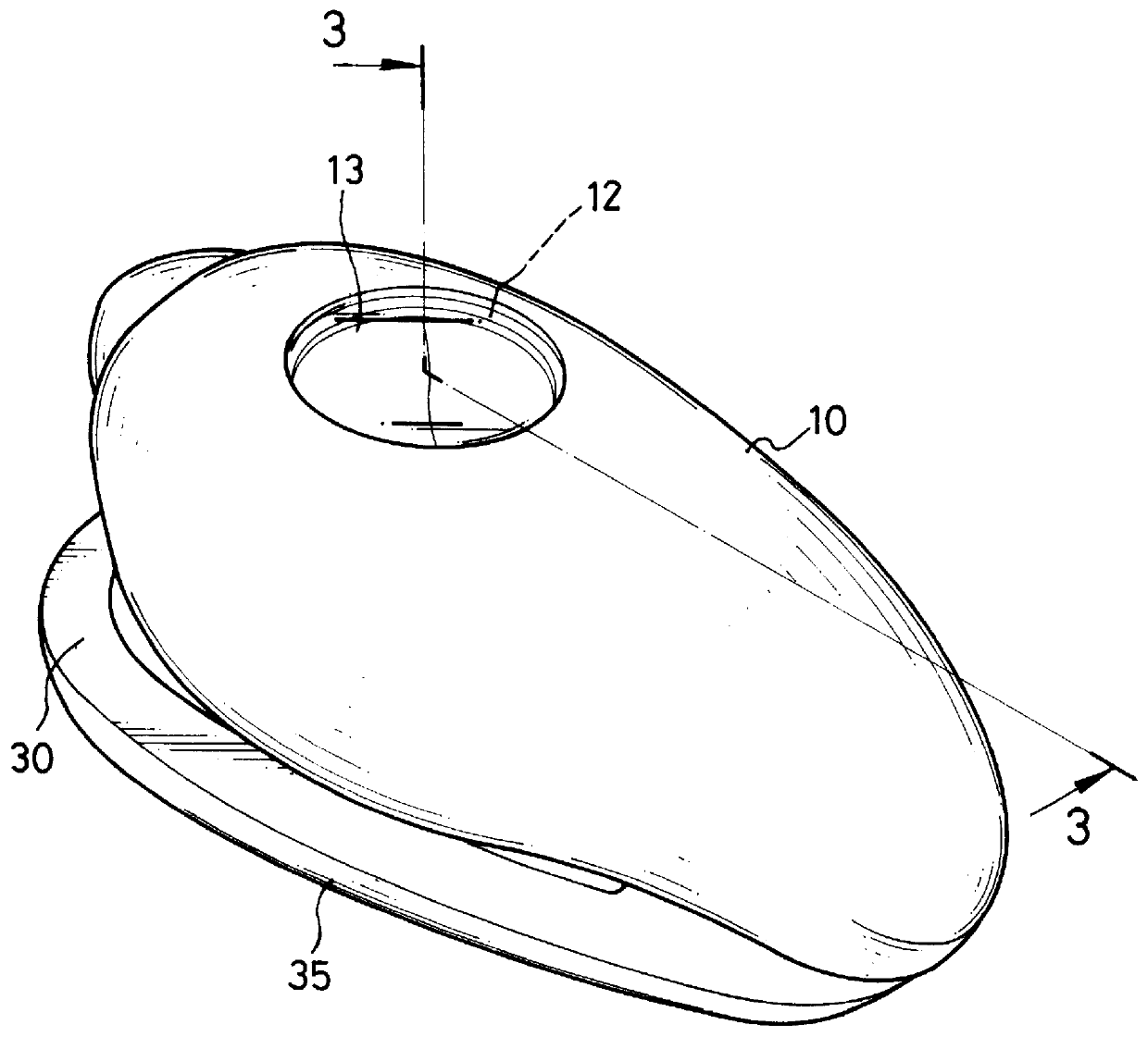
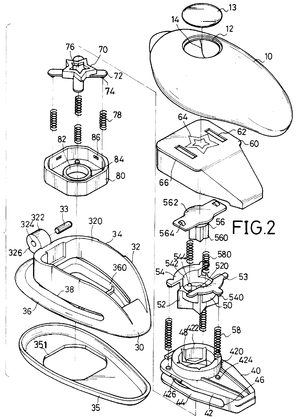
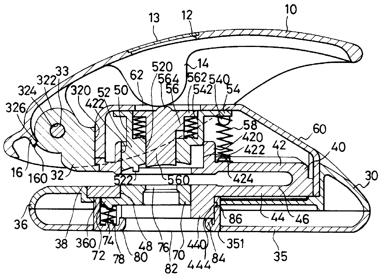
Referring to FIGS. 1 and 2, the punch in accordance with the present invention has a handle (10) with a through hole (12) defined in the top face, a transparent plate (13) detachably mounted on and covering the through hole (12), at least two arcuate plates (14) integrally formed under the handle (10), a base (30) pivotally connected with the handle (10) and a bottom cover (35), which has a first hole (351) defined therethrough, detachably connected under the base (30). The base (30) further has a substantially circular wall (32), a housing (320) defined by the wall (32), a pivot (322) integrally formed on the outer periphery of the wall (32), a bottom (36) integrally formed with the wall (32) and a paper slot (38) defined between the bottom (36) and the wall (32).

A pivot pin hole (324) is defined through the pivot (322) to allow a pin (33) to extend through the pivot pin hole (324) to pivotally connected the handle (10) to the pivot (322). A lip (326) is formed on the outer periphe...


PUM

PropertyMeasurementUnit
transparentaaaaaaaaaa
flexible extensionaaaaaaaaaa
movementaaaaaaaaaa

Abstract

A paper punch has an inner punch and an outer punch movably received with respect to each other. The outer punch has a first contour punch so as to be able to punch a hole in a piece of paper with the same contour as that of the first contour punch, and the inner punch has a second contour punch so as to punch a small hole in a piece of paper with the same contour as that of the second contour punch. Because the second contour punch moves first and the first and the second contour punches are placed concentrically, a piece of paper is then able to be punched twice by the first and the second contour punches to have an attractive shape.

Description

1. Field of the InventionThe present invention relates to a paper punch, and more particularly to a paper punch which is able to punch a hole out a piece of paper with a particular contour and continuously punch out openings on paper with that particular contour.2. Description of Related ArtA paper punch is used to punch out holes in a piece of paper or a stack of suitable material. Although different paper punches are available, the basic structure of a paper punch is is recognizable in virtually all variations, and includes a base, at least one punch rod housing integrally formed on the base, a handle pivotally connected with the punch rod housing and at least one punch rod movably received in the punch rod housing and operatively connected with the handle. A paper slot is defined between the base and the punch rod housing and a hole is defined in the base to correspond to the punch rod, such that when the punch rod is driven by the handle and moved in the punch rod housing, the p...

Claims


Application Information

Patent Timeline
Patent Type & Authority Patents(United States)
IPC IPC(8): B26F1/04B26F1/02B26F1/36
CPCB26F1/04B26F1/36B26D3/10Y10T83/8785Y10T83/8832Y10T83/885Y10T83/9428
Inventor LEE, CHENG-HO
Owner LEE CHENG HO
Why Eureka
Try Eureka