Device for holding and moving a contact image sensor

a technology for contact image sensors and devices, applied in the field of optical scanners, can solve the problems of complex driving mechanism structure and inevitably increase the complexity of the structur

Inactive Publication Date: 2000-07-18
TRANSPACIFIC SYST +1
View PDF8 Cites 42 Cited by
  • Summary
  • Abstract
  • Description
  • Claims
  • Application Information

AI Technical Summary

Benefits of technology

As the contact image sensor is received in the holder and the biasing member is disposed between the holder and the connecting member and does not directly urge the contact image sensor, the contact image sensor can be stably and horizontally received in the holder without inclination.

Problems solved by technology

Inserting an insulation layer between the CIS 141 and the metal biasing member 31 inevitably increases the complexity of the structure.
Supporting the holder 20 with bearings can solve this problem, however, the structure of the driving mechanism becomes complicated.

Method used


Image

  • Device for holding and moving a contact image sensor
  • Device for holding and moving a contact image sensor
  • Device for holding and moving a contact image sensor

Examples


Embodiment Construction

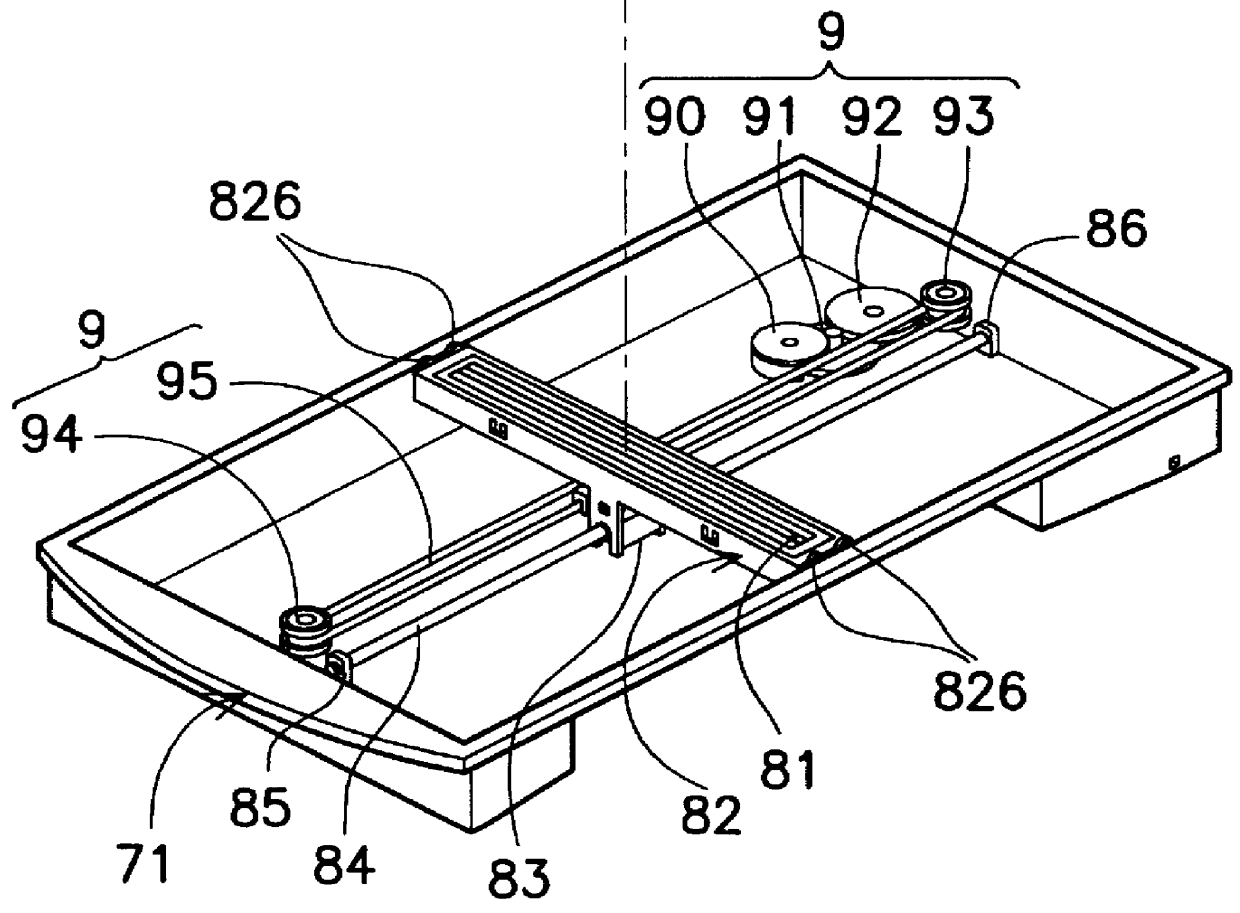
Referring to FIG. 3, the upper frame 72 of the optical scanner of the first embodiment of the invention is substantially rectangular and has a rectangular opening 72H on which a glass plate 720 is mounted. A rectangular lower frame 71 having substantially the same size is used to secure to the upper frame 72 and functions as a base. A holder 82 is supported on the two long sides of the lower frame 71 in parallel to the two short sides of the lower frame 71 by two rollers 826, 826 which are respectively disposed at the two ends of the holder 82, so that the holder can freely slide along the longitudinal axis of the rectangular lower frame 71. A cartridge shaped contact image sensor 81 is received and held in the holder 82. The contact image sensor 81 picks up the image of a detection object, for example a document (not shown) placed on the glass plate 720. The holder 82 is guided by a guiding rod 84. The guiding rod 84 is made of metal and has two ends. The two ends are respectively ...


PUM


Abstract

A contact image sensor is received and held in a holder slidably mounted on a rectangular lower frame and is disposed in parallel to the two short sides of the lower frame to pick up the image of a detection object placed on the transparent plate mounted on a rectangular upper frame. A rod-like guiding member having two ends respectively mounted on the center of the two short sides of the lower frame, disposed orthogonal to the longitudinal holder, for guiding the movement of the holder is provided. A connecting member slidably mounted on the guiding member and detachably connected to the holder near the center thereof is provided. A biasing member for biasing the holder upwardly, disposed between the connecting member and the holder is also provided.

Description

The present invention relates to an optical scanner using a contact image sensor, and in particular to a device for holding and moving a rod-like contact image sensor.DESCRIPTION OF THE PRIOR ARTReferring to FIG. 1 and FIG. 2, a top view and a side sectional view of an optical scanner of Taiwan Patent No. 322,182 are respectively shown. The optical scanner 10 includes a rectangular scanner cover 11, a rectangular upper frame 12 having a glass plate 13 mounted thereon, an opto-mechanical system 14, a rectangular base 15 and a driving mechanism 16. The driving mechanism 16 consists of a drive motor 162, a control interface 161, pulley 163, 163' and a transmission string 164 wrapped on the pulley 163, 163'. The opto-mechanical system 14 includes a rod-like contact image sensor (hereinafter referred to as CIS) 141, a holder 20 for receiving and holding the CIS 141 and a biasing member 31. The holder 20 is cartridge-shaped and bridges on the two long sides of the rectangular base 15. The...

Claims


Application Information

Patent Timeline
Patent Type & Authority Patents(United States)
IPC IPC(8): H04N1/10H04N1/191H04N1/193
CPCH04N1/1017H04N1/1026H04N1/193H04N2201/0442H04N2201/0456
Inventor CHANG, YAO-WENLIN, CHE-YEN
Owner TRANSPACIFIC SYST
Why Eureka
Try Eureka