Density measurement, colorimetric data, and inspection of printed sheet using contact image sensor

a contact image sensor and density measurement technology, applied in the field of density measurement, colorimetric data, and quality assessment of printed matter, can solve the problems of reducing the set-up time of a print job run, inherently expensive stoppage, and industrial printing is a very fast process, so as to reduce the resolution and increase the accuracy

Inactive Publication Date: 2007-08-30
VCORTEX
View PDF9 Cites 21 Cited by
  • Summary
  • Abstract
  • Description
  • Claims
  • Application Information

AI Technical Summary

Benefits of technology

[0041] It is an object of the present invention to provide scanning apparatus for indicating the quality of an image while or shortly after said image is being printed by a printer on a substrate. The apparatus comprises an image processor producing a feedback signal indicating the quality of the image, an illuminator illuminating the substrate, an image sensor measuring light emerging from the substrate, producing a plurality of signals, and comprising a plurality of image sensing elements, with each element located in

Problems solved by technology

Industrial printing is a very fast process and any stoppage is inherently expensive.
Using the adequate profile may considerably decrease the set-up time of a print job run.
This method is disadvantageous for the following reasons:
Delay—the sampling is erratic, it takes the operator 2-3 minutes to pick up a sheet, analyze it and correct the printer settings while the printer is running.
It therefore takes hundreds of sheets of low quality image until a problem is rectified.
Instability—as the sheets may be sampled before the colors have stabled it is possible the coloring is fluctuating faster than the sampling and the correction is performed based on inadequate data, which may lead to over correction and deterioration of the quality.
This method is disadvantageous for the following reasons: Difficult to calibrate—the distance between the camera and the imaged sheet complicates the calibration of the optical system.
Vibration—the large optical distance between the camera and the printed image translates the small vibrations of the press frame into a significant movement of the camera, thus limiting the useful resolution of the camera Human interference—the optical path crosses the area where the operator stands to control the ink-feeding tower.
The operator body and limbs affects the illumination and interfere with the optical path.
This metho

Method used


Image

  • Density measurement, colorimetric data, and inspection of printed sheet using contact image sensor
  • Density measurement, colorimetric data, and inspection of printed sheet using contact image sensor
  • Density measurement, colorimetric data, and inspection of printed sheet using contact image sensor

Examples


Embodiment Construction

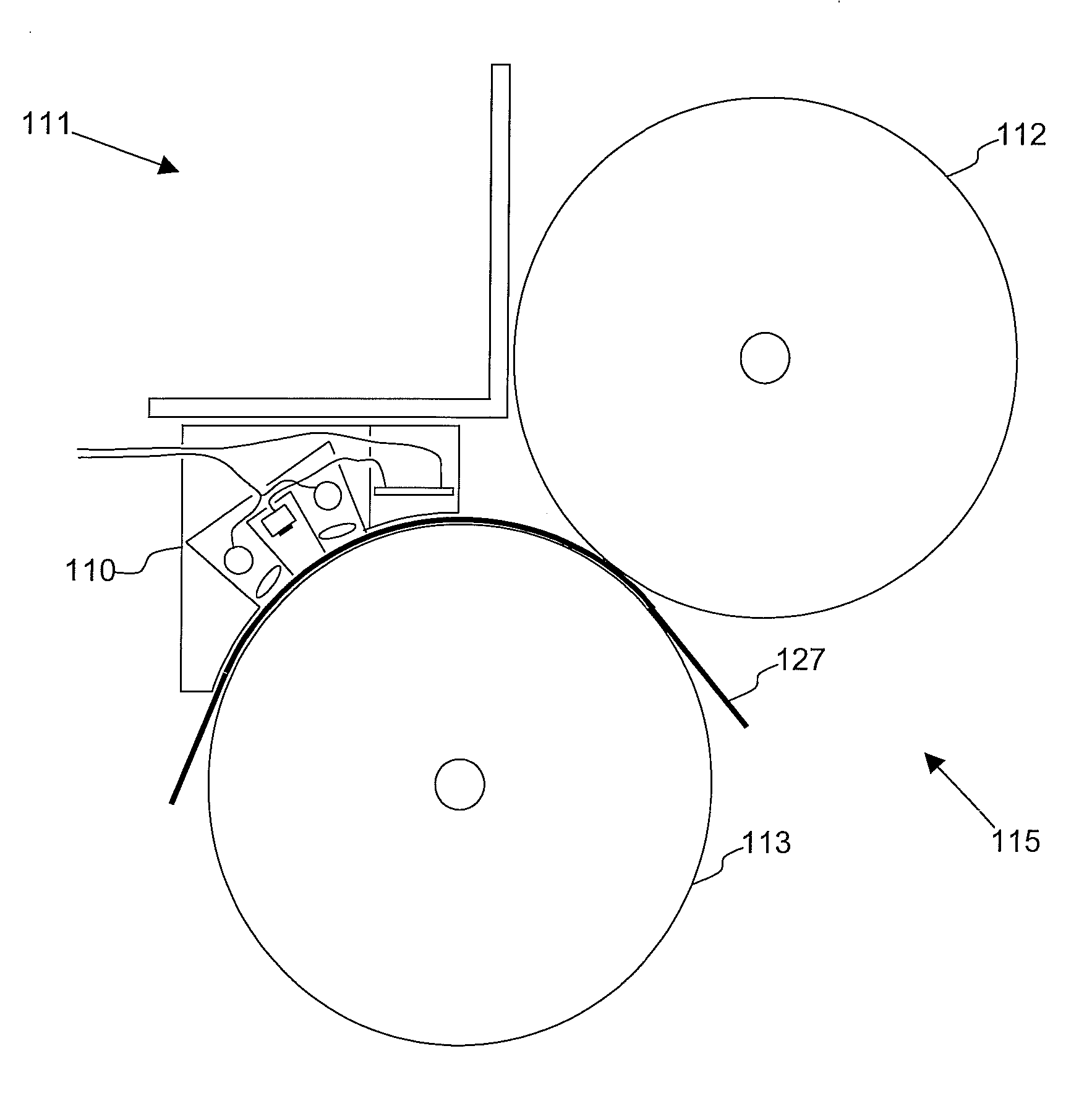
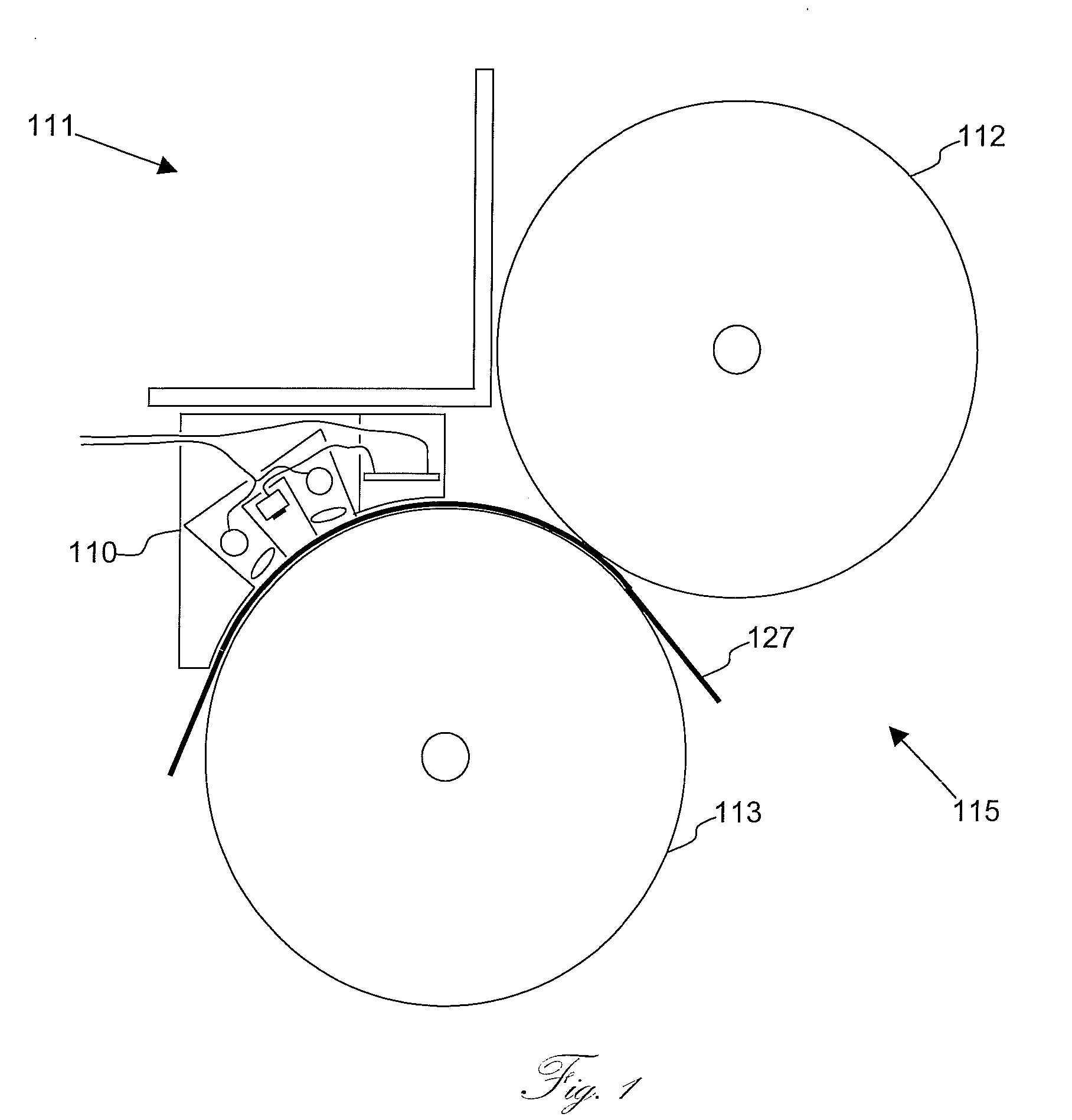
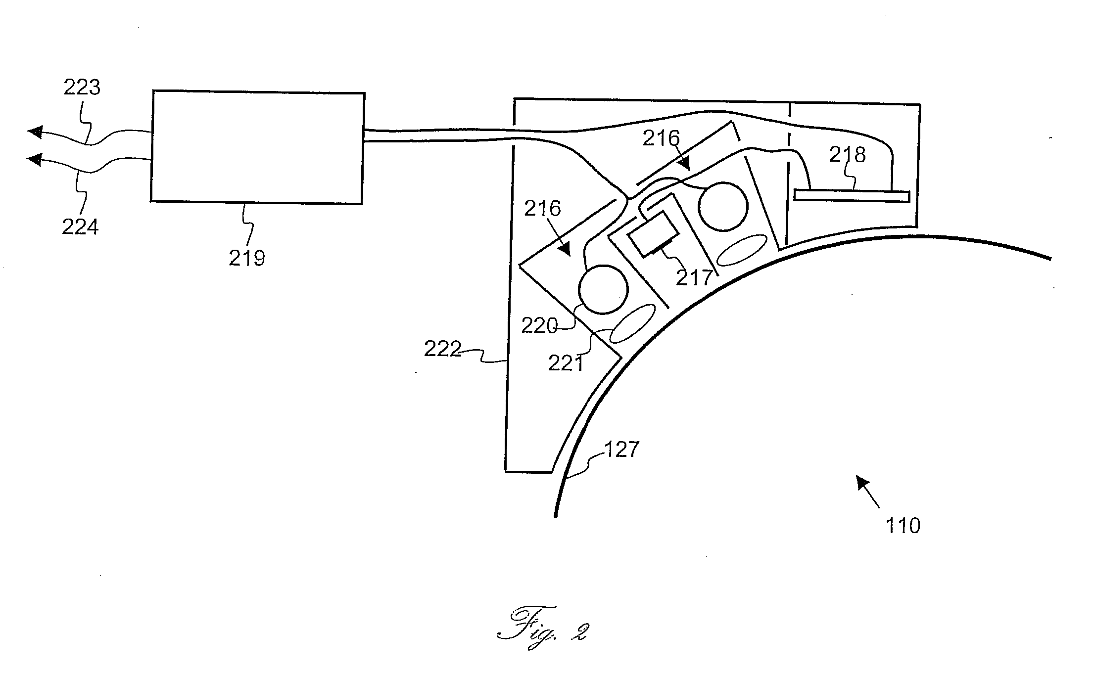
[0091] The present embodiments enable high-speed, high-resolution imaging of a sheet within a sheet-fed offset press, and to use this imaging to assess the quality of the printed image. Particularly, the present embodiments provide information about optical densities, color composition, color registration, etc. Furthermore, the present embodiments provide information regarding the image quality in real-time, to analyze this information and to produce feedback to the printing machine so as to correct drifts in image quality without stopping the printer or decreasing the printing speed. The present embodiments implement illumination elements and light sensors in close proximity to the printed surface and use for this purpose an array of Contact Image Sensors (CIS). Preferably the sensors are connected in parallel so as to output information at high speed and allow real time processing, and the information is fed back to the printing machine to change settings as necessary.

[0092] Cons...


PUM


Abstract

An image quality measurement apparatus measures quality of an image printed on a substrate. The apparatus comprises illumination elements and image sensors, both mounted in close proximity to the substrate, a controller of the image sensors and illumination elements, and an analyzer of the measurements of the image sensor. The measurements can be used as real time feedback to a printer. The measurements may include density, colorimetric data, and inspection of printed sheet using Contact Image Sensors (CIS).

Description

[0001] The present application is a Continuation of PCT / IL2005 / 001130, filed Oct. 30, 2005, which claims the priority of U.S. Provisional application Ser. No. 60 / 622,680, filed Oct. 28, 2004.FIELD AND BACKGROUND OF THE INVENTION [0002] The present invention relates to printing technology and, more particularly, but not exclusively to quality assessment of printed matter, and, even more particularly, but still not exclusively to the assessment of color quality of the printed image. [0003] In the sheet fed printing process of today, whether it is digital printing or legacy offset printing, gravure printing or flexographic printing, there is a need to assess the quality of the printed image within the printing machine. The prime measure of quality is the quality of the colors of the printed image. [0004] As with any other manufacturing process, the sooner a problem is located the simpler it is and the cheaper it is to correct. Industrial printing is a very fast process and any stoppage...

Claims


Application Information

Patent Timeline
IPC IPC(8): H04N1/60
CPCB41F33/0036H04N1/6033G01J3/28
Inventor ZIV, ASA
Owner VCORTEX
Why Eureka
Try Eureka