
Contact image sensor for generating multi-resolutions

a multi-resolution, contact image technology, applied in the field of image sensors, can solve the problems of complex process of fabricating triple optical sensing units, inconvenient cost-effectiveness, and easy shrunken scanning apparatus overall volume, etc., to achieve the effect of cost-effectiveness and simplified volum

Inactive Publication Date: 2007-12-06
PRIMAX ELECTRONICS LTD
View PDF2 Cites 20 Cited by
  • Summary
  • Abstract
  • Description
  • Claims
  • Application Information

AI Technical Summary

Benefits of technology

[0015]It is an object of the present invention to provide a contact image sensor for generating multi-resolutions in a simplified and cost-effective manner.

Problems solved by technology

Unfortunately, since a complex optical system is required for the charge couple device, the overall volume of the scanning apparatus is not easily shrunken.
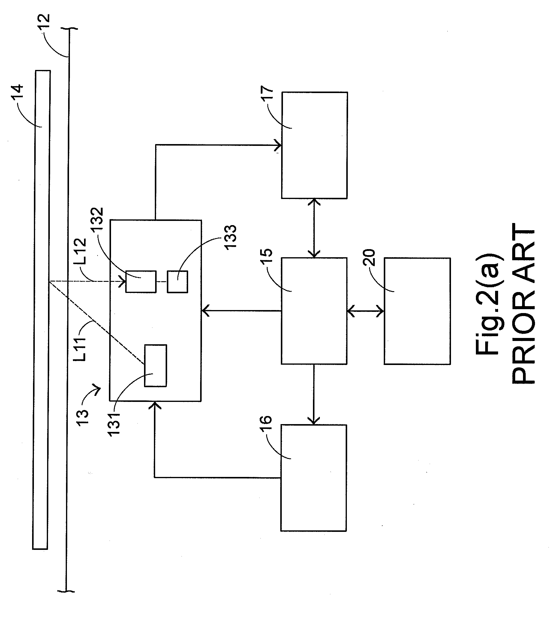
Since the length of the optical sensing element 133 is limited, the process of fabricating triple optical sensing units becomes more complicated and is not cost-effective.

Method used


Image

  • Contact image sensor for generating multi-resolutions
  • Contact image sensor for generating multi-resolutions
  • Contact image sensor for generating multi-resolutions

Examples


Embodiment Construction

[0032]The present invention will now be described more specifically with reference to the following embodiments. It is to be noted that the following descriptions of preferred embodiments of this invention are presented herein for purpose of illustration and description only. It is not intended to be exhaustive or to be limited to the precise form disclosed.

[0033]Please refer to FIGS. 4 and 5. FIG. 4 is a schematic perspective view of a CIS scanning apparatus 30 according to the present invention. FIG. 5 is a schematic diagram illustrating the scanning operation concept of the CIS scanning apparatus 30. The CIS scanning apparatus 30 includes a casing 31, a transparent platform 32 and a contact image sensor (CIS) 33. The transparent platform 32 is disposed on the upper surface of the casing 31 and used for placing thereon the document 34 to be scanned. The CIS scanning apparatus 30 further comprises a control member 35, a driving member 36 and a storage member 37, which are also incl...


PUM


Abstract

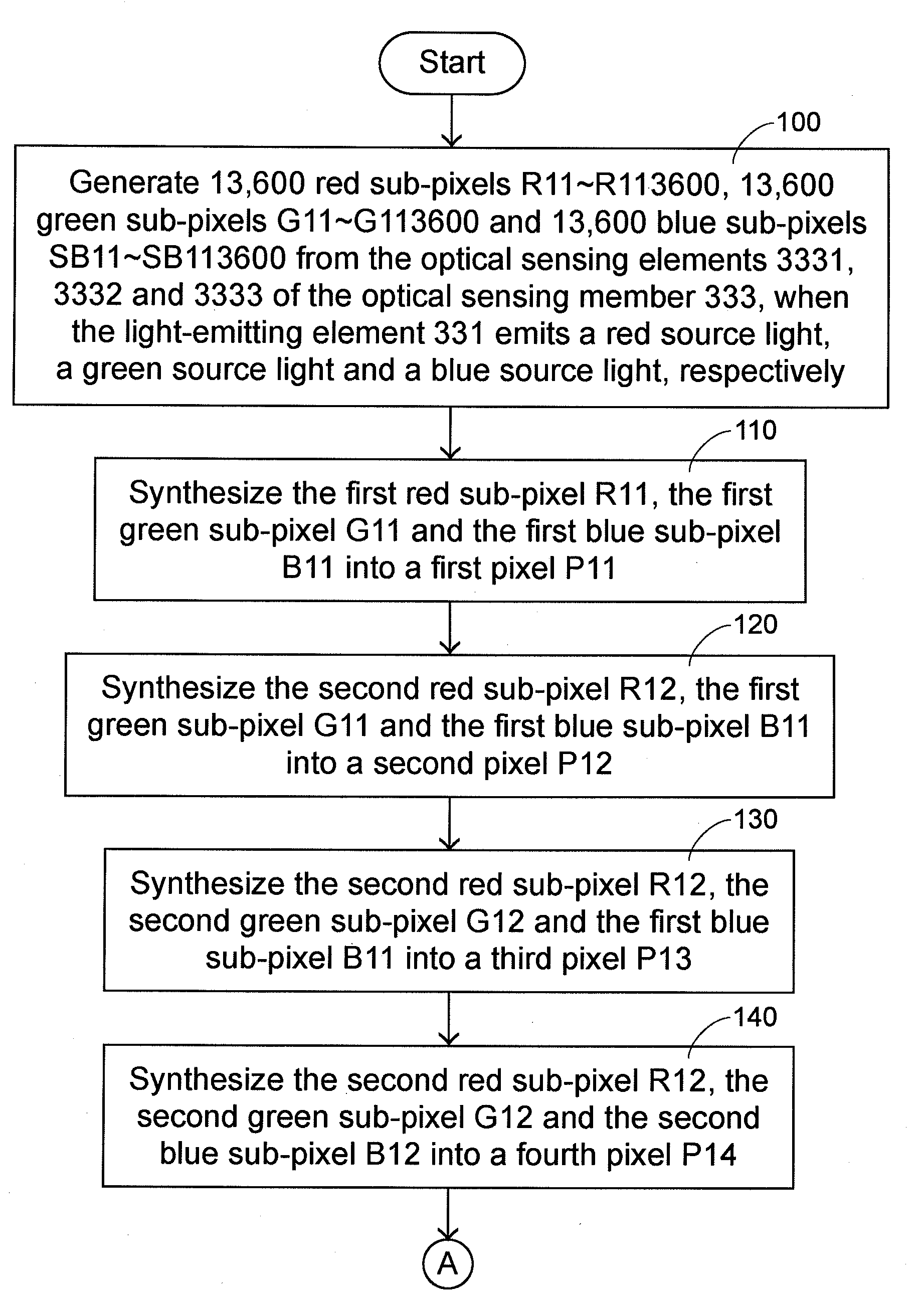
A contact image sensor includes a first optical sensing element and at least one additional optical sensing element. The first optical sensing element includes plural optical sensing units arranged in a line along a first direction. Plural first image units are successively generated when the first optical sensing element senses a first source light. The at least one additional optical sensing element is disposed at a lateral side of the first optical sensing element, and includes plural optical sensing units arranged in a line along the first direction. When the additional optical sensing element senses an additional source light, plural additional image units are successively generated. The adjacent optical sensing units of the first optical sensing element and the at least one additional optical sensing element are partially overlapped with each other along a second direction, which is perpendicular to the first direction.

Description

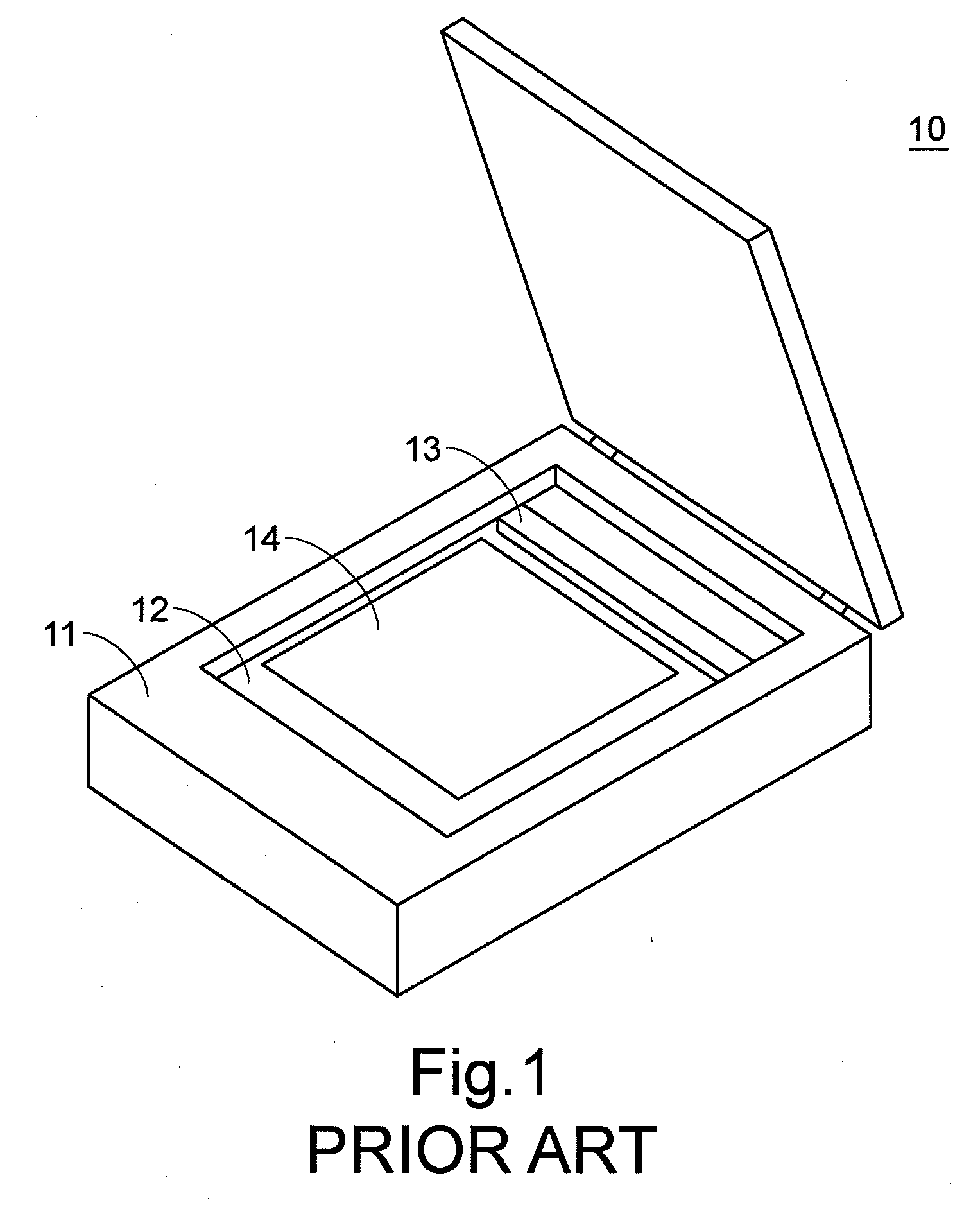
FIELD OF THE INVENTION[0001]The present invention relates to an image sensor, and more particularly to a contact image sensor for generating multi-resolutions.BACKGROUND OF THE INVENTION[0002]Scanning apparatuses are commonly used in offices or homes for scanning for example documents, photographs, graphs or films. The scanned images can be converted into digital electronic files, which are then stored in a computer. Moreover, some digitalized processing operations such as digital display, editing, saving and outputting operations may be performed on the digital electronic files by the computer.[0003]Generally, the optical sensors used in the scanning apparatuses are classified into two types, i.e. a charge couple device (CCD) and a contact image sensor (CIS). Since the charge couple device has a relatively higher scanning speed, the charge couple device is commonly used in the scanning apparatus. Unfortunately, since a complex optical system is required for the charge couple device...

Claims


Application Information

Patent Timeline
Patent Type & Authority Applications(United States)
IPC IPC(8): H04N1/46
CPCH04N1/0402H04N1/0411H04N1/0455H04N1/486H04N1/1933H04N1/1934H04N1/1017
Inventor FENG, CHANG-YUNGLIN, HUNG-TSE
Owner PRIMAX ELECTRONICS LTD
Learn More