Method for increasing single-pulse range resolution

a single-pulse, range resolution technology, applied in distance measurement, surveying and navigation, instruments, etc., can solve the problems of limiting the range resolution, and imposing the task of even modern-day electronics

Inactive Publication Date: 2000-09-05
LOCKHEED MARTIN CORP
View PDF9 Cites 152 Cited by
  • Summary
  • Abstract
  • Description
  • Claims
  • Application Information

AI Technical Summary

Problems solved by technology

Both of these types suffer from threshold uncertainties and a variety of other problems.
This would be a formidable task for even modern day electronics.
However, this technique is typically limited by hardware whose operational speed constrains the sampling rate.
Further, ...

Method used


Image

  • Method for increasing single-pulse range resolution
  • Method for increasing single-pulse range resolution
  • Method for increasing single-pulse range resolution

Examples


Embodiment Construction

Illustrative embodiments of the invention are described below. In the interest of clarity, not all features of an actual implementation are described in this specification. It will of course be appreciated that in the development of any such actual embodiment, numerous implementation-specific decisions must be made to achieve the developers' goals, such as compliance with system-related and business-related constraints, which will vary from one implementation to another. Moreover, it will be appreciated that such a development effort, even if complex and time-consuming, would be a routine undertaking for those of ordinary skill in the art having the benefit of this disclosure.

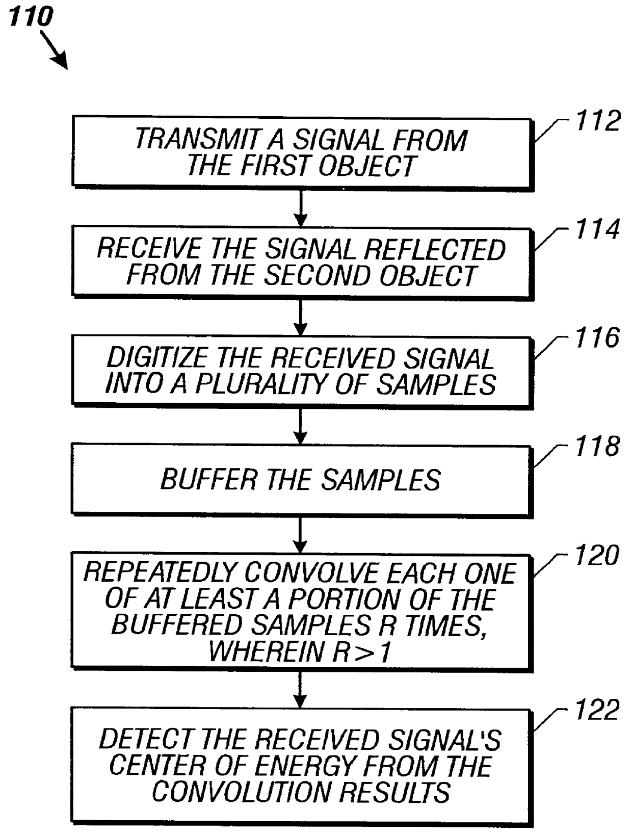
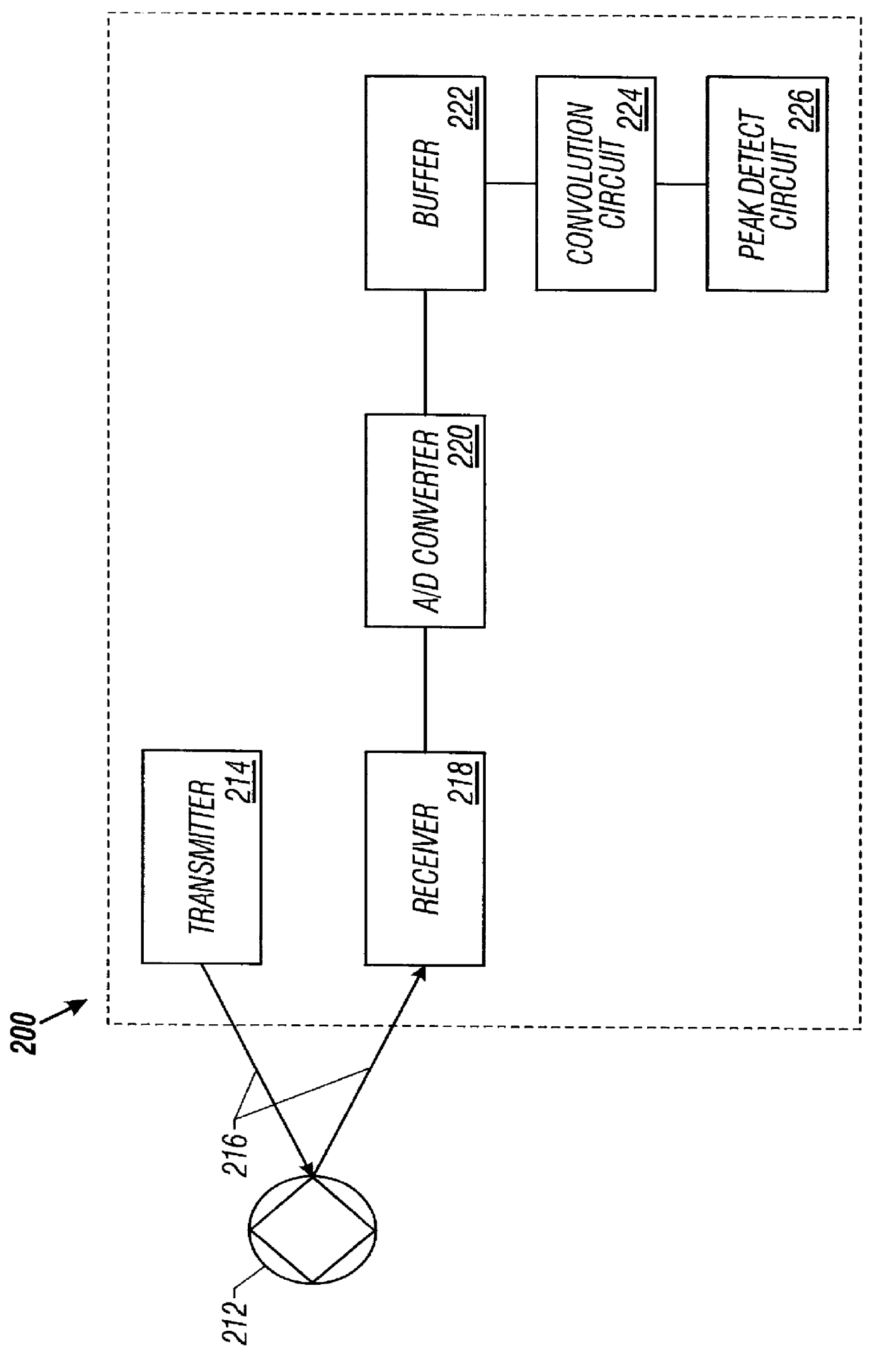
FIGS. 1 and 2 illustrate a method 110 and apparatus 200, respectively, of an exemplary embodiment of the present invention. The apparatus 200 senses, receives, and processes one or more energy pulses reflected from an object 212 to the receiver 218 of the apparatus 200 in accordance with the method 110. The tra...


PUM


Abstract

A method and apparatus is provided for detecting a pulse in a signal. In one aspect of the invention, a method comprises digitizing the signal into a plurality of samples; repeatedly convolving each one of at least a portion of the buffered samples R times, wherein R>1; and detecting the received signal's center of energy from the convolution results. In a second aspect, an apparatus comprises a analog-to-digital converter capable of digitizing the received signal to produce a plurality of samples; a convolution circuit, including a matched filter for convolving the digitized signal at a second sampling rate; a buffer capable of storing the samples and serially outputting each of the samples R times, where R>1, to the convolution circuit; and a detector for detecting the digitized signal's center of energy from the output of the convolution circuit.

Description

1. Field of the InventionThis invention relates generally to processing information from a received signal and, more particularly, to increasing range resolution in a LADAR system.2. Description of the Related ArtOnce common application for laser technology is laser detecting and ranging (LADAR) systems. In LADAR systems, brief laser pulses are generated and transmitted via a scanning mechanism. Some of the transmitted pulses striking a target of interest are reflected back to a receiver associated with the transmitter. The time between the transmission of a laser pulse and the receipt of the reflected laser pulse ("return pulse") is used to calculate the "range" from the object that reflected the laser pulse to the object that receives the return pulse.There are several types of known LADAR systems. In one type, electronic circuitry begins a ramp function concurrently with the transmission of the outgoing pulse. The ramp function halts when the return pulse is received. Thus, the h...

Claims


Application Information

Patent Timeline
IPC IPC(8): G01S17/10G01S17/00G01S7/48G01S7/487G01S7/481
CPCG01S7/4812G01S7/487G01S17/10G01S7/4817
Inventor FLOCKENCIER, STUART W.
Owner LOCKHEED MARTIN CORP
Why Eureka
Try Eureka