Bearing assembly

a technology of bearing assembly and bearing assembly, which is applied in the direction of bearing unit rigid support, manufacturing tools, mechanical equipment, etc., can solve the problems of increasing the complexity and cost unwanted movement or creep of the bearing assembly,

Inactive Publication Date: 2000-10-10
VISTEON GLOBAL TECH INC
View PDF11 Cites 38 Cited by
  • Summary
  • Abstract
  • Description
  • Claims
  • Application Information

AI Technical Summary

Problems solved by technology

In operation of the fluid compressor device, the compressor housing and the bearing assembly proximate the orbiting scroll/fixed scroll can experience elevated temperatures to an extent that unwanted movement or creep of the bearing assembly can occur relative to the compressor ...

Method used


Image

  • Bearing assembly

Examples


Embodiment Construction

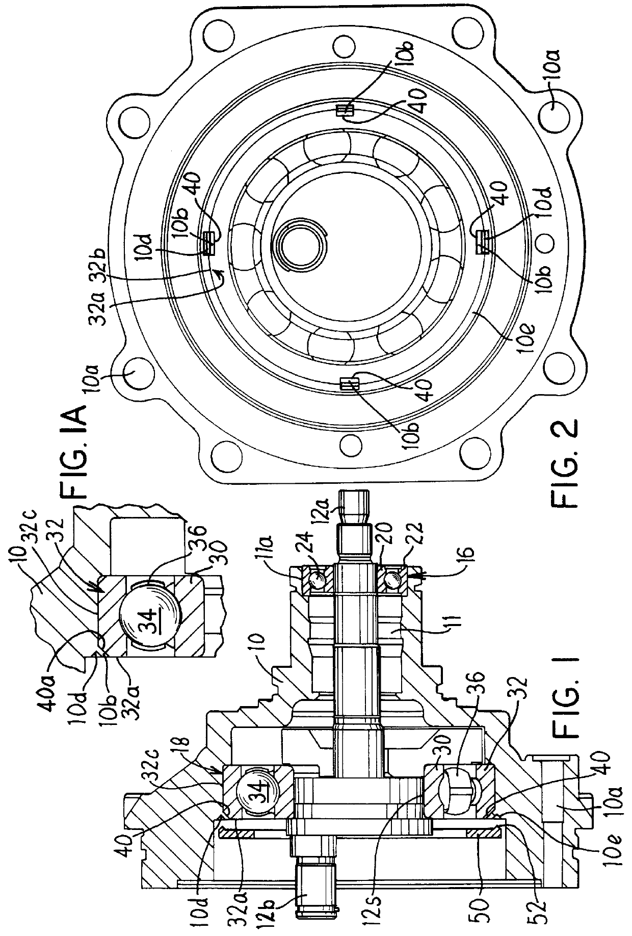
FIGS. 1 and 2 illustrate a compressor front housing 10 and drive shaft 12 of a conventional scroll type rotary fluid compressor of a vehicle air conditioning device. A driven end 12a of the drive shaft 12 is connected to an electric or other drive clutch (not shown) for rotation of a conventional orbiting scroll rotor (not shown) connected to an opposite eccentric driving end 12b of the drive shaft. The front housing 10 is fastened to a conventional rear housing (not shown) via fasteners received in fastener holes 10a in a manner that the orbiting scroll rotor can be translated by shaft 12 relative to a fixed scroll (not shown) to achieve compression of a working fluid (e.g. refrigerant) as described, for example, in U.S. Pat. No. 4,365,941.

The drive shaft 12 is rotatably mounted in a stepped bore 11 of the housing 10 by first and second ball bearing assemblies 16, 18 that are press fit in the housing proximate opposite ends 12a, 12b of the shaft 12 as illustrated. Bearing assembly ...


PUM


Abstract

A bearing assembly comprises a bearing race received in a bore of a housing comprising a deformable housing material. The bearing race includes one or more recesses formed on a surface thereof disposed proximate the housing. Each recess receives housing material that has been deformed locally therein after the bearing race is received in the bore to prevent both rotational and axial motion of the bearing race relative to the housing.

Description

1. Field of the InventionThe present invention relates to a bearing assembly in which a bearing race is mounted in a housing in a manner to prevent rotation and axial motion of the race relative to the housing.2. Background InformationIn a scroll type fluid compressor of a vehicle air conditioning device, an electric clutch is connected to a drive shaft for rotation of an orbiting scroll relative to a fixed scroll in a manner to achieve working fluid compression. The drive shaft is rotatably mounted in an aluminum housing of the compressor device by conventional bearing assemblies press fit in a bore of the housing proximate opposite ends of the shaft.In operation of the fluid compressor device, the compressor housing and the bearing assembly proximate the orbiting scroll / fixed scroll can experience elevated temperatures to an extent that unwanted movement or creep of the bearing assembly can occur relative to the compressor housing as a result of the considerably higher coefficient...

Claims


Application Information

Patent Timeline
IPC IPC(8): B21K25/00F16C35/067F16C35/04
CPCB21K25/00F16C35/067Y10T29/49682F16C19/06F16C9/02F16C19/56F16C33/586F16C2360/42F16C2226/50
Inventor GALANTE, CHRISTOPHER ROBERT
Owner VISTEON GLOBAL TECH INC
Why Eureka
Try Eureka