Hand held control key device including multiple switch arrangements
a control key and switch arrangement technology, applied in the field of control key devices, can solve the problems of hand fatigue, inconvenient operation,
- Summary
- Abstract
- Description
- Claims
- Application Information
AI Technical Summary
Problems solved by technology
Method used
Image

Examples
first embodiment
With reference to figures, a control-key device in the present invention will now be described.
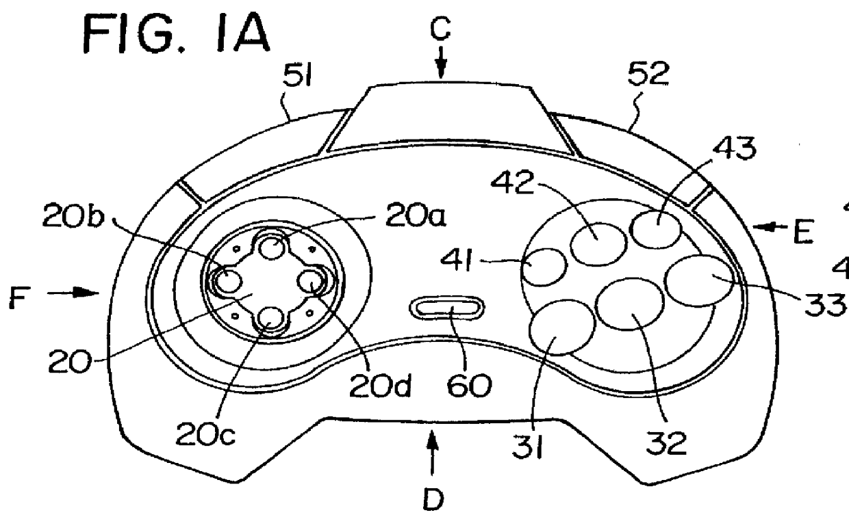
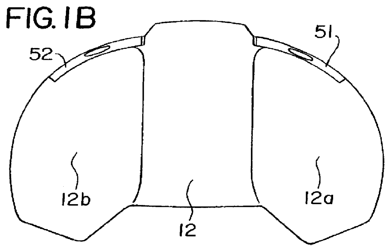
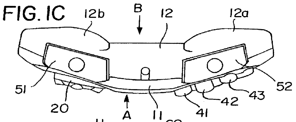
FIGS. 1A, 1B, 1C, 1D, 1E, and 1F shows the control-key device 10 in a first embodiment of the present invention. FIG. 1A shows a plan view, FIG. 1B shows a bottom view, FIG. 1C shows a rear view obtained as a result of viewing along a direction C of FIG. 1A, FIG. 1D shows a front view obtained as a result of viewing along a direction D of FIG. 1A, FIG. 1E shows a right side elevational view obtained as a result of viewing along a direction E of FIG. 1A, and FIG. 1F shows a left side elevational view obtained as a result of viewing along a direction F of FIG. 1A. Further, FIG. 2 shows a state in which an operator is holding the control-key device 10 using two hands of the operator.
The control-key device 10 has a top case 11 and a bottom case 12. As shown in FIGS. 1C and 1D, the entirety of the control-key device 10 is curved so that bottom case 12 may be located at a side of the curving cen...
second embodiment
With reference to FIG. 12, a control-key device 100 in the present invention will now be described. FIG. 12 shows a longitudinal sectional view of the control-key device 100.
The control-key device 100 has functions approximately equivalent to those of the control-key device 10 in the first embodiment of the present invention in view of operating contents thereof. In a top case 111 thereof, similar to the top case 11 of the device 10, the left and right thereof are inclined downward in FIG. 12. However, a circuit substrate 180 relevant to the circuit substrates 81, 82 and 83 of FIG. 3 has a plane shape in a state in which it has been assembled into the device 100. Therefore, a rubber contact member 170 relevant to the rubber contact member 70 of FIG. 3 and a rubber contact member 122 relevant to the rubber contact member 22 of FIG. 3 are placed along the horizontal direction in FIG. 12.
In order to cause them to match this structure, an axis of each of A, B and C buttons 131, 132, 133...
third embodiment
A control-key device 210 in the present invention will now be described.
This control-key device 210 has a structure similar to that of the above-described control-key device 10 in the first embodiment of the present invention. Therefore, only parts different from relevant parts in the control-key device 10 in the first embodiment will be described and description for the parts having the same structures will be omitted.
The parts, in the structure of the control-key device 210 in the third embodiment, different from the structure of the control-key device 10 in the first embodiment are as follows: First, shapes of an L button 251 and an R button 252 shown in FIGS. 13A through 13F, and 14 are different from the shapes of the L button 51 and R button 52 in the control-key device 10 in the first embodiment, respectively. Next, shapes of button guiding portions 236, 237 238, 246, 247, 248 shown in FIG. 14 for guiding movement of the A, B, C buttons 31, 32, 33 and X, Y, Z buttons 41, 42, ...
PUM
 Abstract
Description
Claims
Application Information
 - Generate Ideas
- Intellectual Property
- Life Sciences
- Materials
- Tech Scout
- Unparalleled Data Quality
- Higher Quality Content
- 60% Fewer Hallucinations
Browse by: Latest US Patents, China's latest patents, Technical Efficacy Thesaurus, Application Domain, Technology Topic, Popular Technical Reports.
© 2025 PatSnap. All rights reserved.Legal|Privacy policy|Modern Slavery Act Transparency Statement|Sitemap|About US| Contact US: help@patsnap.com