Electrical drive unit

a technology of electric drive and drive unit, which is applied in the direction of vehicle maintenance, vehicle cleaning, transportation and packaging, etc., can solve the problems of requiring a great deal of joining directions for assembling the various prefabricated component units or individual parts, and affecting the service life of the vehicl

Inactive Publication Date: 2000-12-19
ROBERT BOSCH GMBH
View PDF6 Cites 50 Cited by
  • Summary
  • Abstract
  • Description
  • Claims
  • Application Information

AI Technical Summary

Problems solved by technology

A problematic aspect of these drive units is the relatively complicated and hence expensive assembly of many separate individual parts.
In particular, assembling the various prefabricated component units or individual parts requires a great many joining directions.
Mounting the brushes contacting the commutator proves to be especially problematic.
Not only does this complicated mode of assembly require some skill; it is also a hindrance, especially to assembling the electrical drive unit by machine.

Method used


Image

  • Electrical drive unit
  • Electrical drive unit
  • Electrical drive unit

Examples


Embodiment Construction

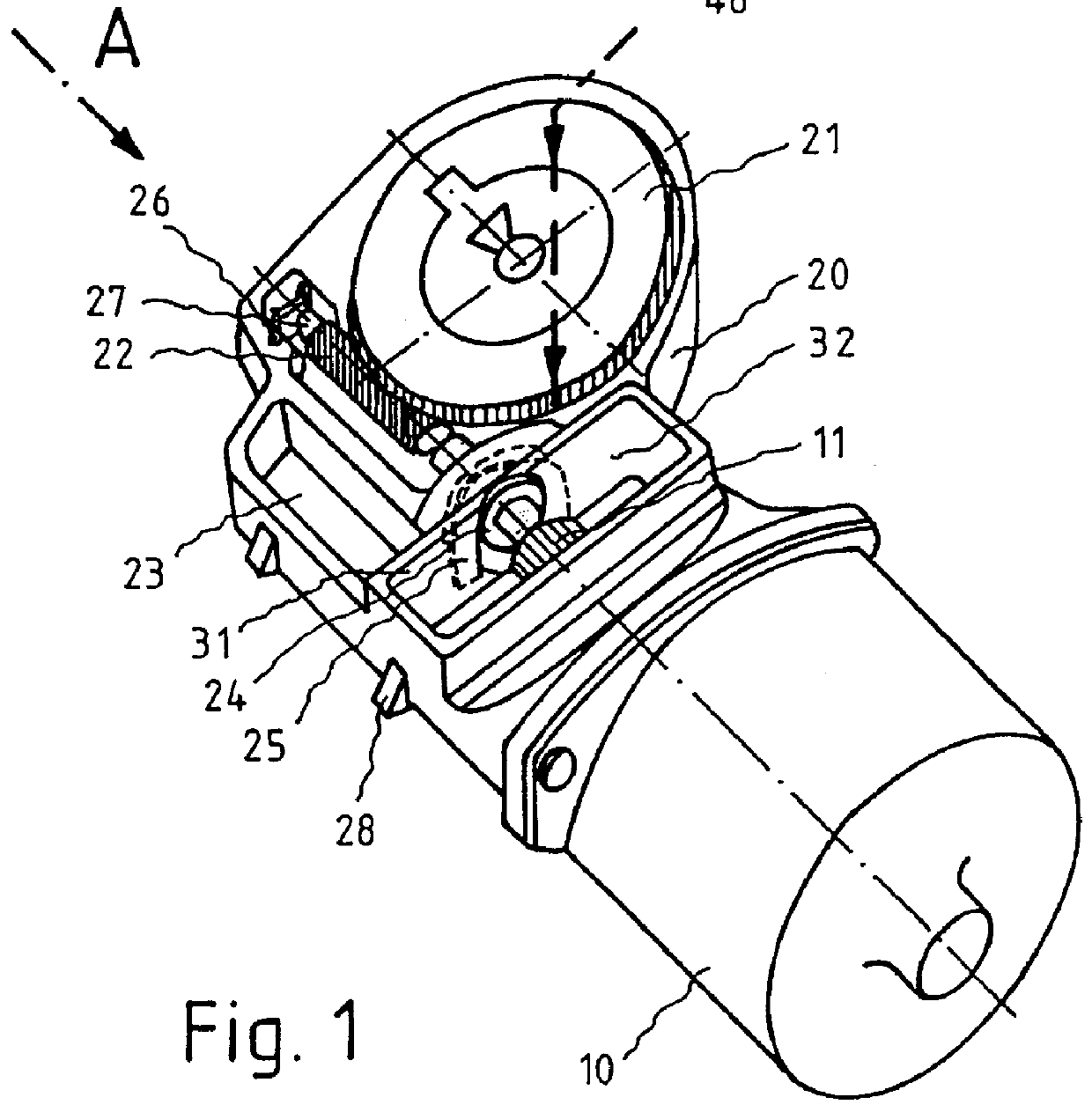
An electrical drive unit for windshield wipers of a motor vehicle, shown in FIG. 1, includes a pole housing 10, in which permanent magnets and an armature winding, disposed rotatably on an armature shaft, and optionally a ring manget disposed on the armature shaft and other parts, known per se, of an electric motor (not shown) are accommodated.

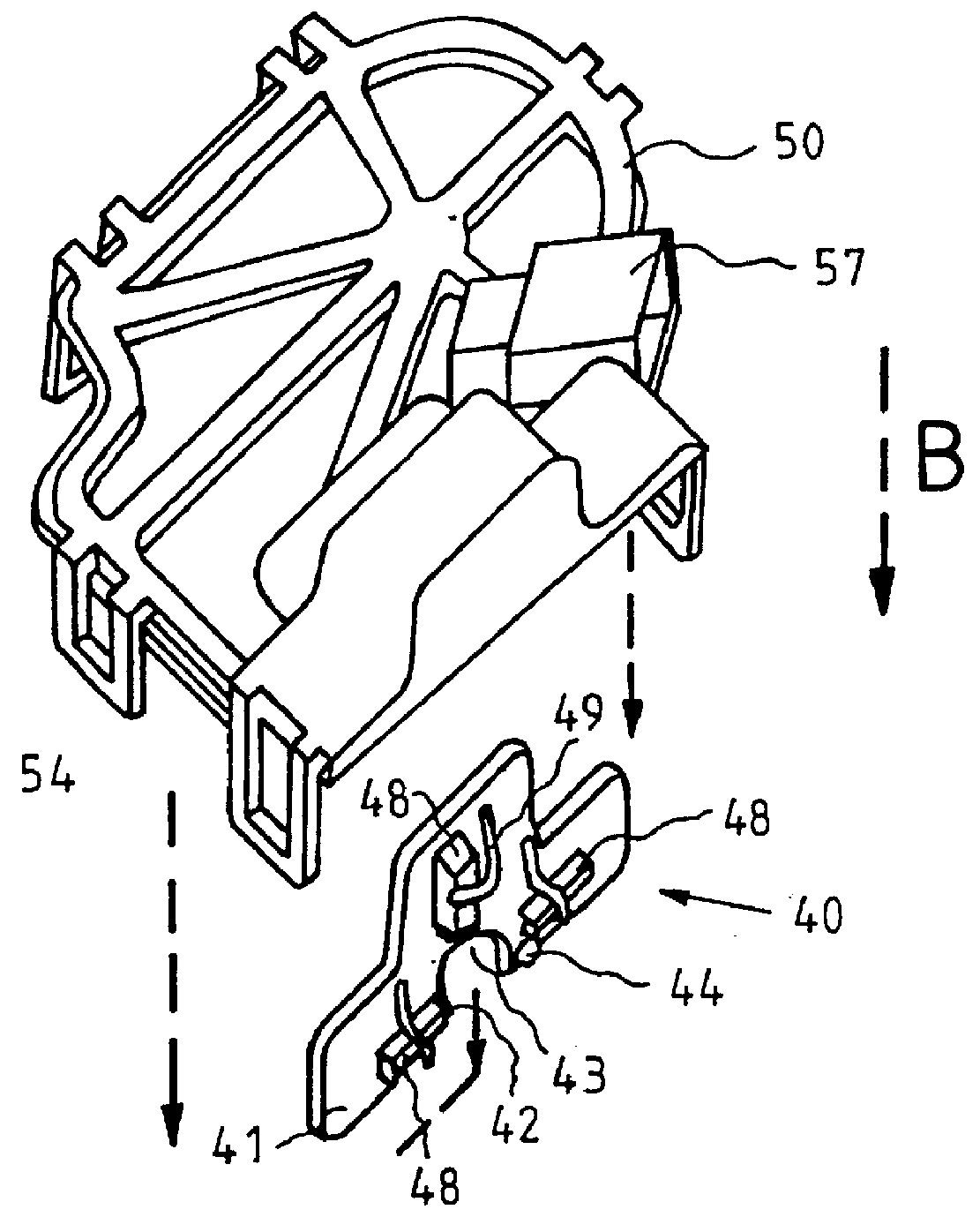
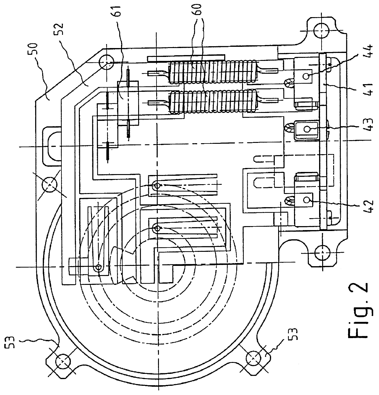
A substantially cup-shaped gearbox 20 is secured to a flange on the face end of the pole housing 10. Gear elements, namely a gear wheel 21, which engages a worm 22 connected to the armature shaft of the drive motor, are disposed in the gearbox 20. The gearbox 20 has an opening 31, on its side toward the pole housing 10, through which the commutator 11 is disposed in freely accessible fashion. Also provided in the gearbox 20, adjacent to the worm 22, is a pocket 23, in which interference suppression elements 60, 61, which are secured to a gearbox cover 50 (see FIG. 2), are disposed in the mounted state of the gearbox cover 50.

As can also be see...


PUM


Abstract

PCT No. PCT/DE98/01532 Sec. 371 Date Feb. 26, 1999 Sec. 102(e) Date Feb. 26, 1999 PCT Filed Jun. 5, 1998 PCT Pub. No. WO99/00885 PCT Pub. Date Jan. 7, 1999An electrical drive unit for windshield wipers of a motor vehicle, including a drive motor which has an armature accommodated in a substantially cup-shaped housing, and a substantially cup-shaped gearbox for receiving gear elements which is secured on a face end to the housing and is closable by a gearbox cover. A closable opening is provided in the gearbox or housing, through which opening a brush holder support that holds commutator brushes can be pushed in a radial direction onto the commutator of the drive motor.

Description

PRIOR ARTThe invention relates to an electrical drive unit, in particular for windshield wipers of a motor vehicle, including a drive motor which has an armature accommodated in a substantially cup-shaped pole housing, and a substantially cup-shaped gearbox for receiving gear elements which is secured on its face end to the motor housing and is closable by a gearbox cover.Such electric switch elements are known for instance from German Patent Disclosures DE 32 20 191 A1 and DE 32 35 622 A1, German Patent DE 39 30 144 C2, and German Patent Disclosure DE 41 16 100 A1.A problematic aspect of these drive units is the relatively complicated and hence expensive assembly of many separate individual parts. In particular, assembling the various prefabricated component units or individual parts requires a great many joining directions. Mounting the brushes contacting the commutator proves to be especially problematic. In the known devices, these brushes are secured to annular brush holder sup...

Claims


Application Information

Patent Timeline
Patent Type & Authority Patents(United States)
IPC IPC(8): B60S1/08H02K5/14H02K7/116H02K11/02H02K11/00H02K13/00
CPCB60S1/166H02K5/148H02K11/024H02K11/00H02K7/1166H02K11/026H02K11/028H02K5/14
Inventor MICHENFELDER, GERHARDLAUK, DETLEFFISCHER, ERNSTKARCHER, HANSJOERGHERP, JUERGENHURST, RICHARD
Owner ROBERT BOSCH GMBH
Why Eureka
Try Eureka