Geometry translation processor

a technology of geometry and translation processor, applied in the field of geometry translation processor, can solve problems such as performance and efficiency degradation

Inactive Publication Date: 2001-01-16
KK TOSHIBA
View PDF4 Cites 21 Cited by
  • Summary
  • Abstract
  • Description
  • Claims
  • Application Information

AI Technical Summary

Problems solved by technology

The clipping test of the prior art involves many comparison and branching steps, to deteriorate performance and efficiency.

Method used


Image

  • Geometry translation processor
  • Geometry translation processor
  • Geometry translation processor

Examples


Embodiment Construction

FIG. 4 shows a graphics processing system employing a geometry translation processor according to an embodiment of the present invention.

The system has a processor unit 1, a graphics processor unit (GPU) 3, and a main memory 5, which are connected to one another through a main bus 7. The GPU 3 is connected to a graphics memory 9 through a graphics bus 11.

The GPU 3 has a pre-process part 13 and a main process part 15. The main process part 15 employs digital differential analyzers (DDAs), to read texture information from the graphics memory 9, carry out rendering on pixels, and write a resultant image in a frame buffer in the graphics memory 9. The pre-process part 13 calculates parameters such as initial and differential values for the DDAs of the main process part 15.

The processor unit 1 has a processor core 17, which reads a program from the main memory 5 and executes the same. According to the program, the processor core 17 generates GPU command information such as the two-dimens...


PUM


Abstract

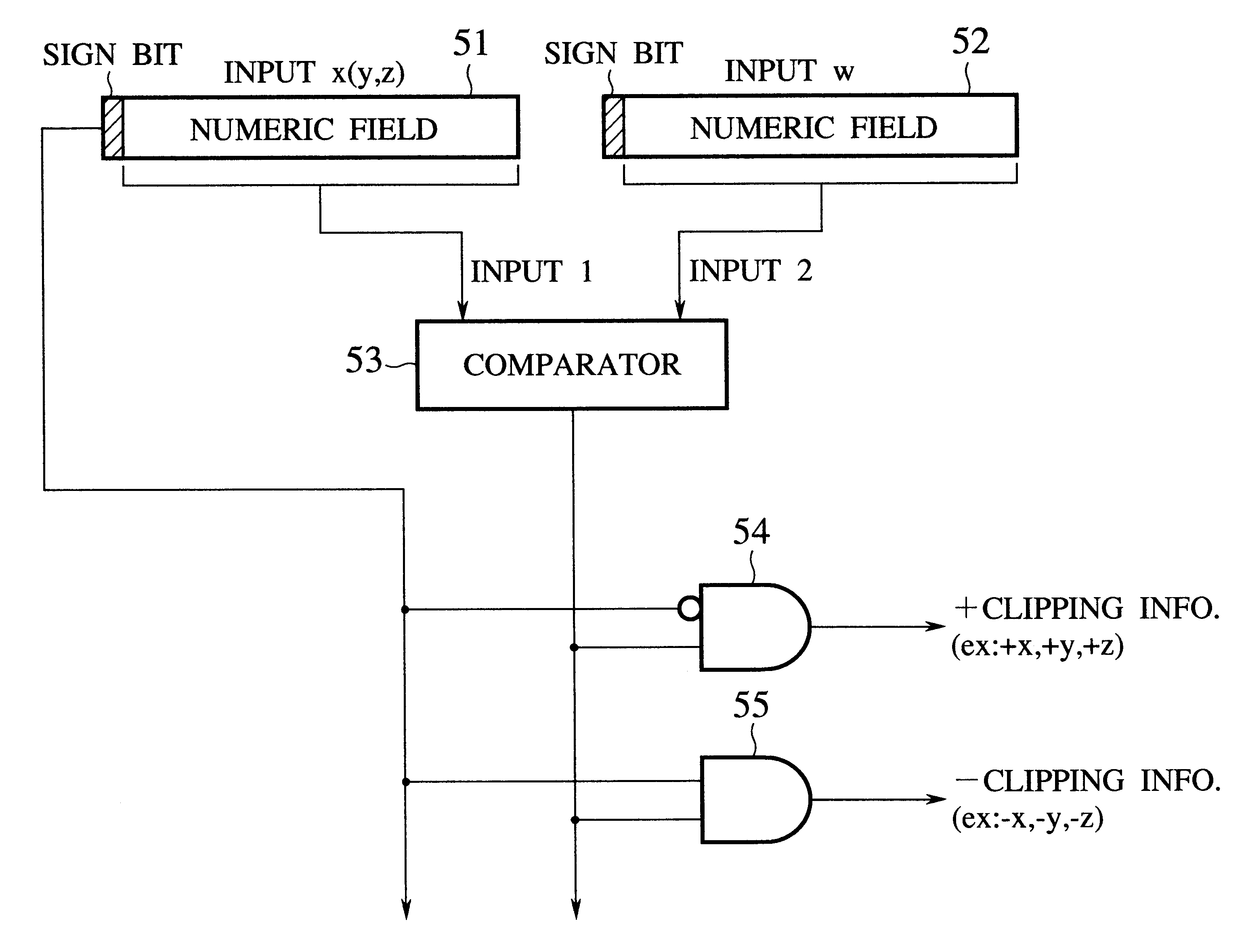
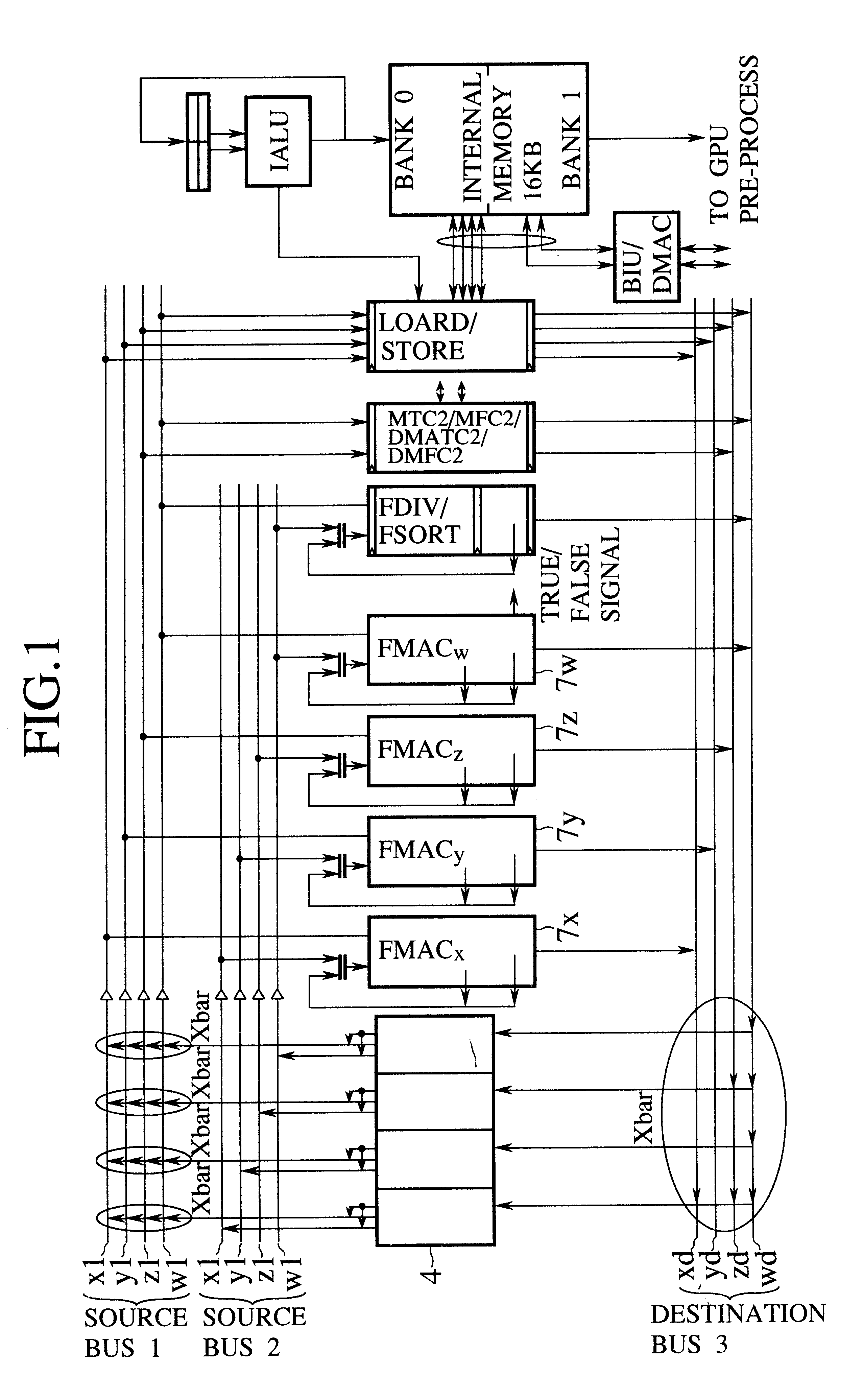
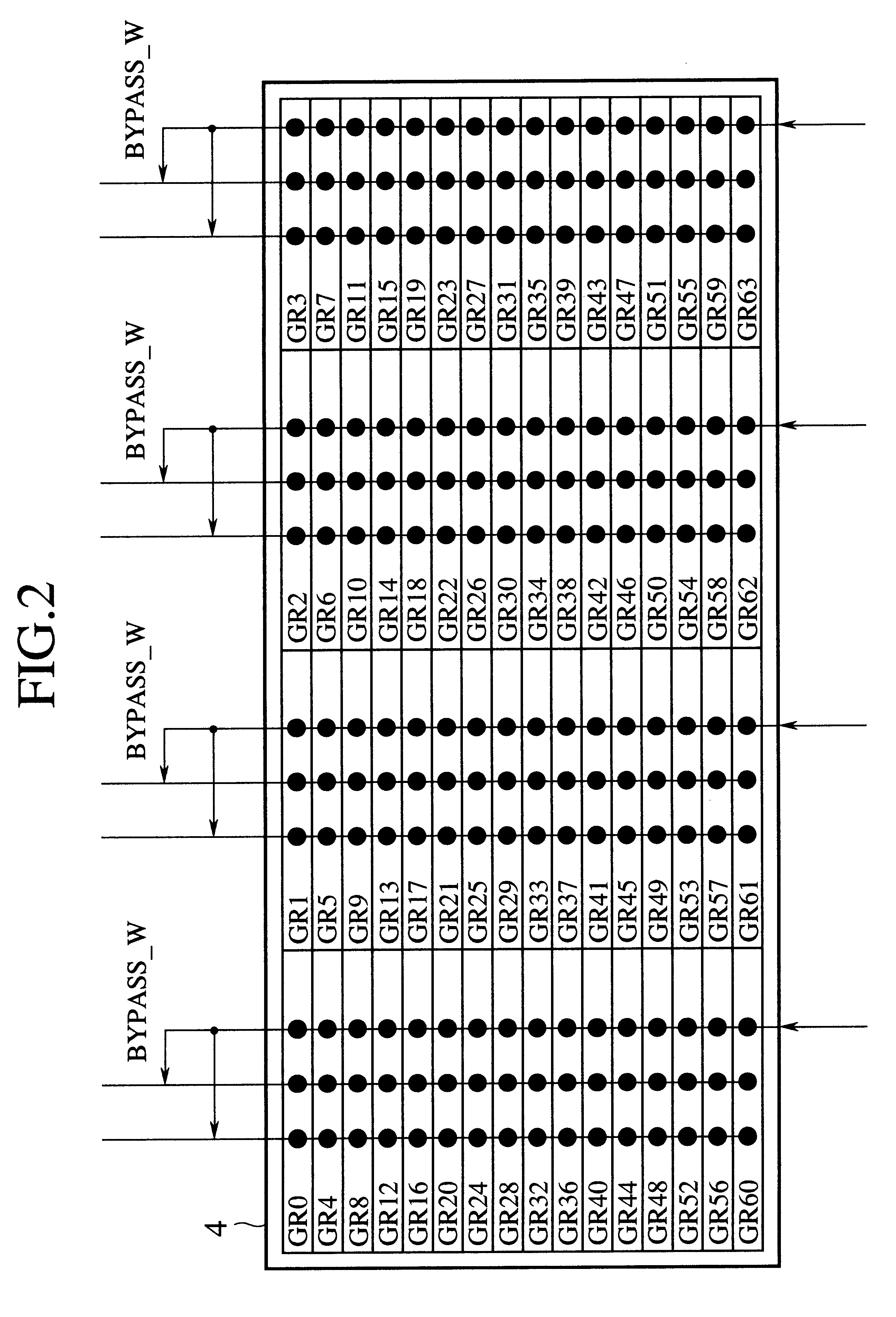
A geometry translation processor used when drawing a polygon on a display translates coordinates and efficiently carries out a clipping test to determine whether or not the polygon must be clipped on the display. The processor has operation units (5x, 5y, 5z), clipping comparators (4x, 4y, 4z) provided for the operation units, respectively, and a clipping register (6). The clipping comparators compare the elements (xn, yn, zn) of a translated coordinate vector with the remaining element (wn) of the same vector. The clipping register is used to store the outputs of the clipping comparators and speedily carry out the clipping test.

Description

1. Field of the InventionThe present invention relates to a geometry translation processor incorporated in a floating-point processor, for carrying out geometry translation when drawing graphics on a display.2. Description of the Prior ArtWhen drawing a polygon on a display, it is necessary to translate the three-dimensional coordinates of each vertex of the polygon into two-dimensional ones. The translation is achieved by calculating the product of a 4-by-4 matrix and a 4-element vector. After the translation, each vertex of the polygon is checked to see if it is within a display area, to determine whether the vertex must be clipped or displayed as it is.For example, an output coordinate vector (x', y', z', w') is obtained as the product of an input coordinate vector (x, y, z, 1) and the following matrix: ##EQU1##The product is calculated as follows: ##EQU2##The calculation is executed at high speed with four multiply-add calculation units by operating them four times in parallel. ...

Claims


Application Information

Patent Timeline
Patent Type & Authority Patents(United States)
IPC IPC(8): G06T15/30G06T15/10
CPCG06T15/30
Inventor KUNIMATSU, ATSUSHI
Owner KK TOSHIBA
Why Eureka
Try Eureka