Hydraulic coupling with pressure-energized dovetail seal

a technology of hydraulic couplings and dovetail seals, applied in the direction of hose connections, water supply installations, couplings, etc., can solve the problems of increasing the complexity and cost of seals, insufficient seals alone,

Inactive Publication Date: 2001-01-30
NAT COUPLING
View PDF26 Cites 61 Cited by
  • Summary
  • Abstract
  • Description
  • Claims
  • Application Information

AI Technical Summary

Problems solved by technology

While seals having a dovetail interfit prevent blowing out or implosion of the seal into the bore of the female member, the seal alone is insufficient in certain applications.
However, the use of two or more seals and the structural design of the hydraulic coupling for such seals increases in complexity and cost when two or more seals are employed.

Method used


Image

  • Hydraulic coupling with pressure-energized dovetail seal
  • Hydraulic coupling with pressure-energized dovetail seal
  • Hydraulic coupling with pressure-energized dovetail seal

Examples


Embodiment Construction

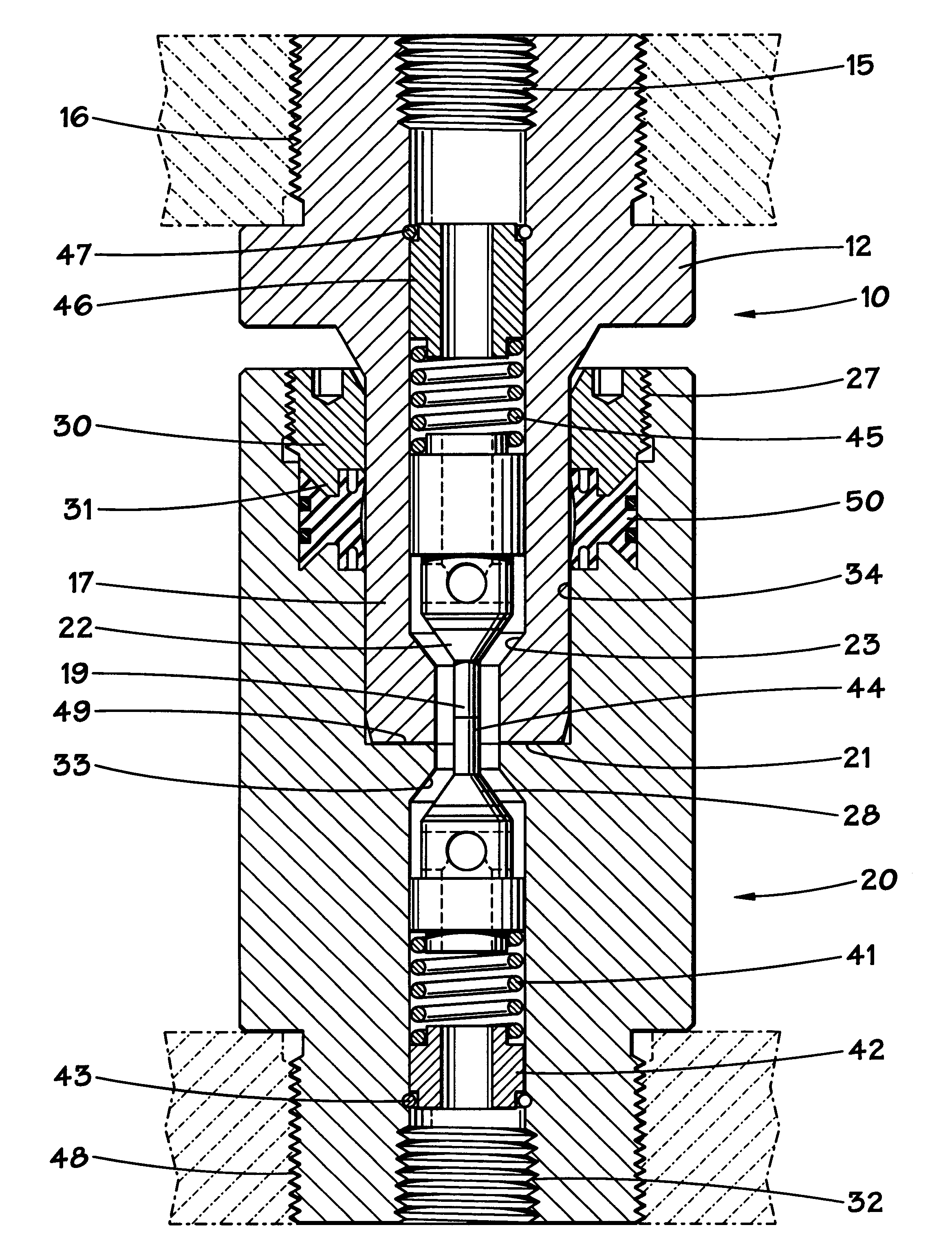
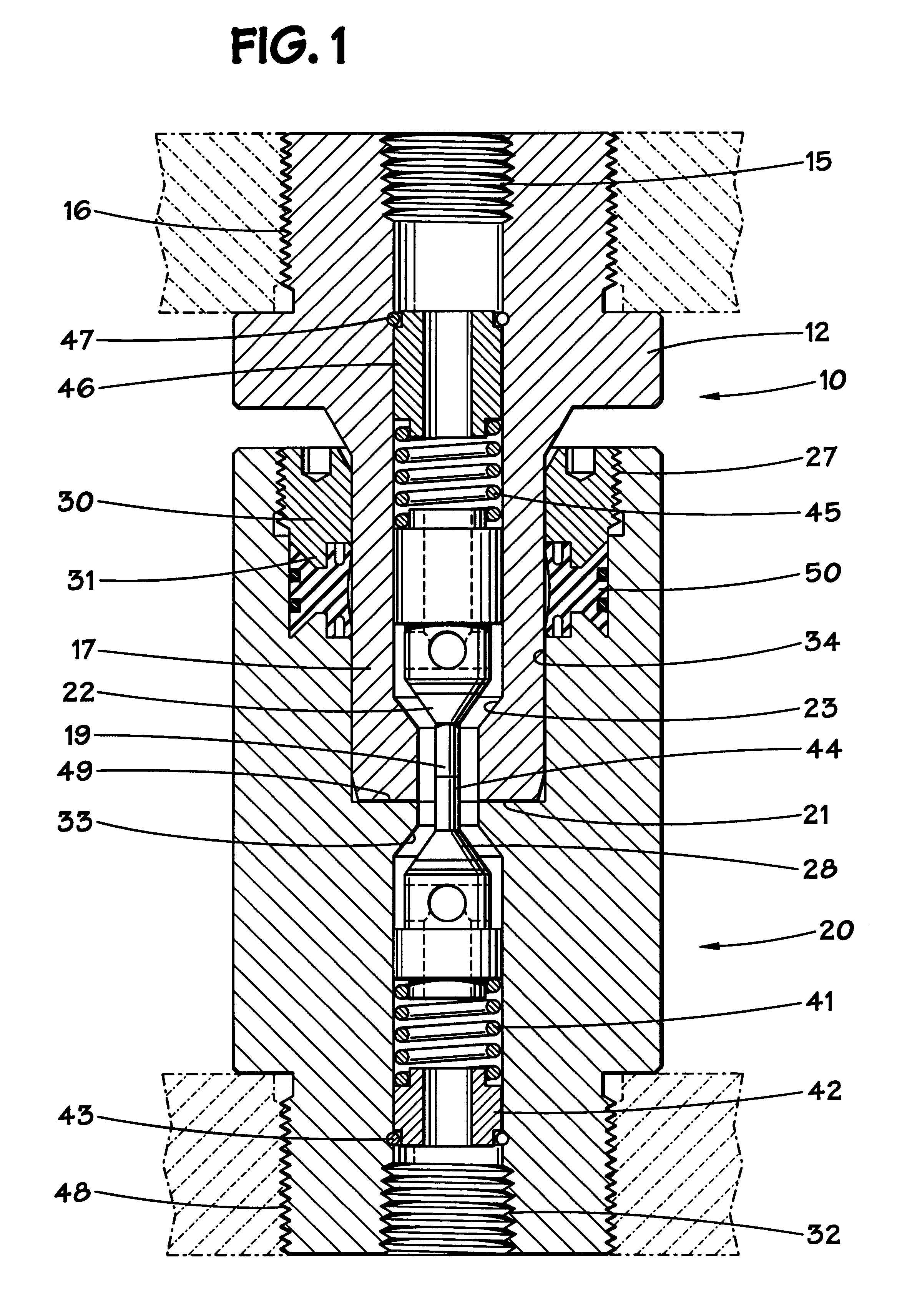
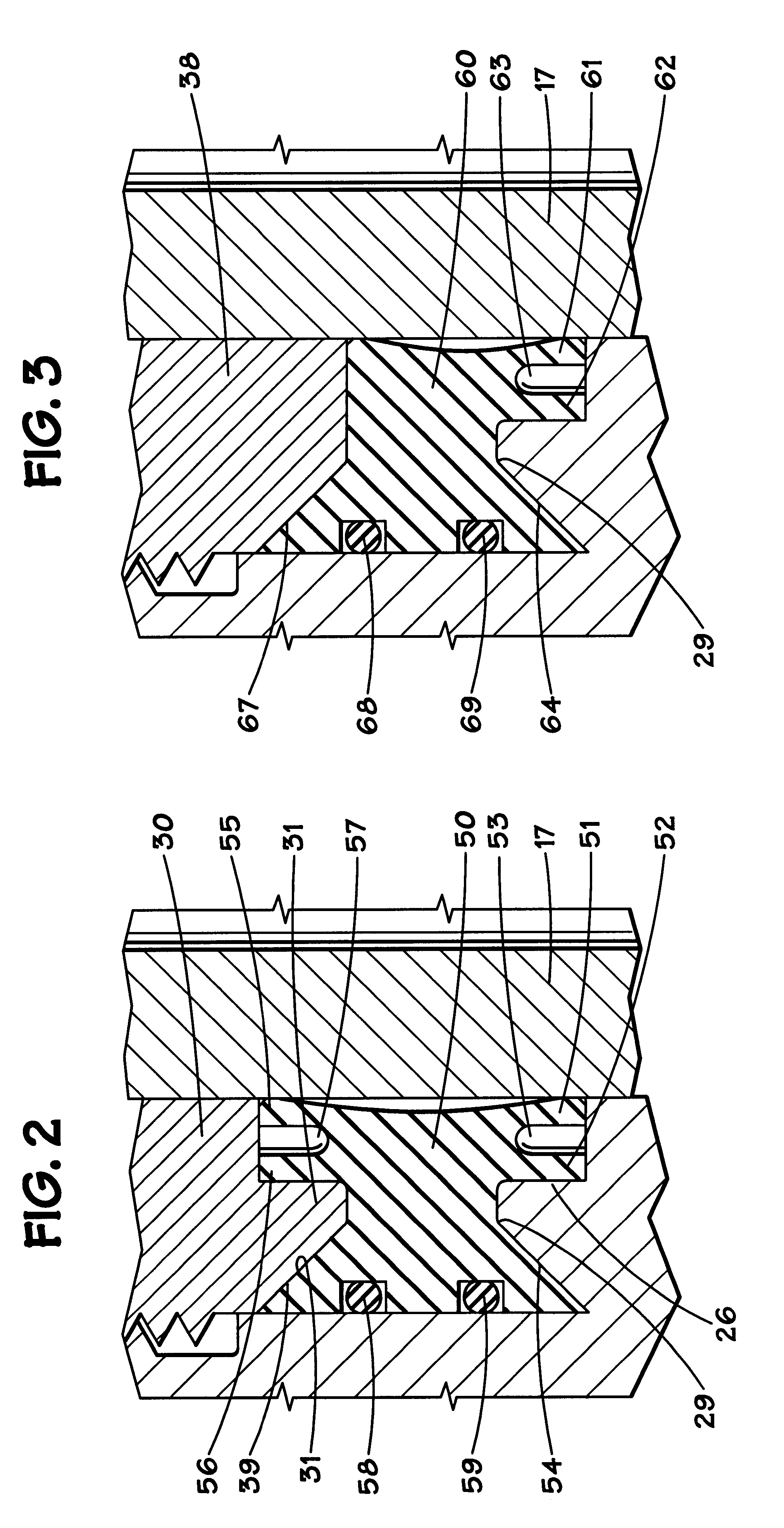
Undersea hydraulic couplings are generally connected to opposing plates of a manifold and are held together by bolts or hydraulic members attached to the plates. The male and female members may be attached to the opposing plates using various means, such as set screws or threads. Techniques for attaching members to such plates are well known to those skilled in the art.

As shown in FIG. 1, in a first preferred embodiment, the male member 10 comprises a threaded handle 16, which may be attached to a manifold plate. The handle terminates at flange 12 of the male member, which adjoins probe 17 and terminates at probe face 21. The cylindrical probe 17 is adapted for sliding engagement with the female member 20 and seal retainer 30 as will be described below. The body of the male member also is provided with a central bore 15. The bore 15 may have several variations in its diameter as it extends through the body of the male member. In a preferred embodiment, the first end of the central b...


PUM


Abstract

An undersea hydraulic coupling having a radial pressure-energized seal with a dovetail interfit is disclosed. The seal has a pair of flexible sealing surfaces for sealing with the male and female coupling members, and a cavity therebetween that is exposed to fluid pressure in the coupling. The outer circumference of the seal has a dovetail interfit between inclined shoulders in the female member bore and on a seal retainer that holds the seal in the bore.

Description

1. Field of the InventionThis invention relates, in general, to hydraulic couplings, and specifically to hydraulic couplings used in undersea drilling and production applications. More particularly, the invention involves an undersea hydraulic coupling having an improved radial seal with a dovetail interfit for holding and positioning the seal in place upon separation of the male member from the female member of the coupling.2. Description of the Related ArtSubsea hydraulic couplings are old in the art. The couplings generally consist of a male member and a female member with seals to seal the junction between the male and female members. The female member generally has a cylindrical body with a relatively large diameter bore at one end and a relatively small diameter bore at the other. The small bore facilitates connections to hydraulic lines, while the large bore contains the seals and receives the male portion of the coupling. The male member includes a probe section insertable i...

Claims


Application Information

Patent Timeline
Patent Type & Authority Patents(United States)
IPC IPC(8): F16L29/04F16L17/00F16L29/00F16L17/035
CPCF16L1/26F16L29/04F16L17/035Y10S285/917Y10T137/87925Y10T137/87957
Inventor SMITH, III, ROBERT E.
Owner NAT COUPLING
Why Eureka
Try Eureka