
Blower

a blower and blower technology, applied in the field of blowers, can solve the problems of noise level and air flow vs. static pressure characteristics deterioration, loss is great, and flow is liable to be separated

Inactive Publication Date: 2001-02-06
PANASONIC CORP
View PDF5 Cites 51 Cited by
  • Summary
  • Abstract
  • Description
  • Claims
  • Application Information

AI Technical Summary

Problems solved by technology

In this zone, loss is great, and the flow is liable to be separated.
The air flow is separated from the blade surface, so that vortexes are produced in the separation region, by which turbulence noise is increased, and the noise level and the air flow vs. static pressure characteristics deteriorate.
However, the blower with slits has a problem in that the air flow at low pressure is slightly small, and the power (a value obtained by multiplying driving torque by rotational speed, hereinafter referred to as a fan driving force) at the time when the fan is driven at the same rotational speed is high, so that the fan static pressure efficiency (a value obtained by multiplying static pressure by air flow and dividing by fan driving force) is decreased.

Method used


Image

  • Blower
  • Blower
  • Blower

Examples


Embodiment Construction

An embodiment of the present invention will be described below with reference to FIGS. 1 to 8.

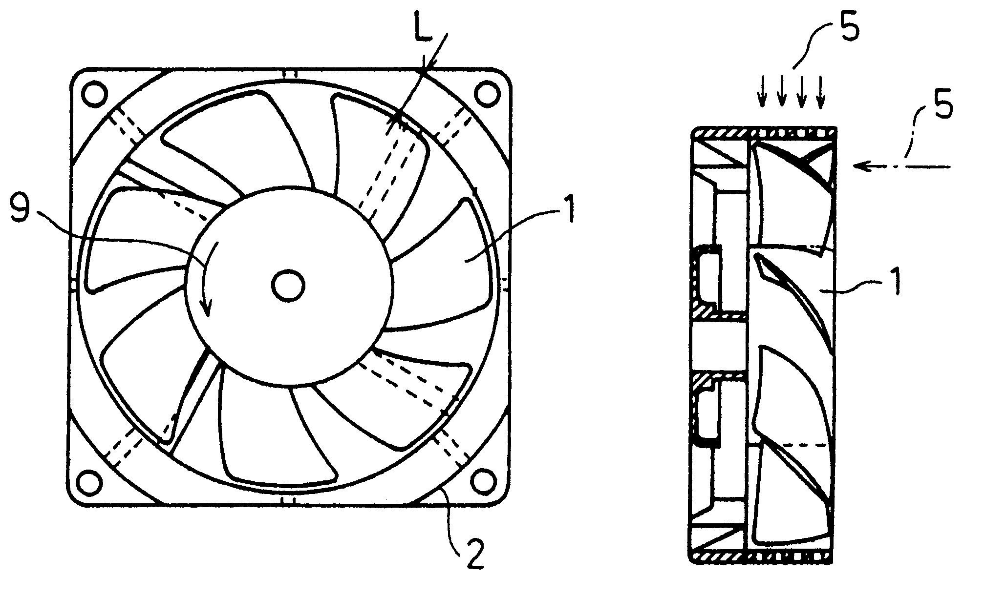
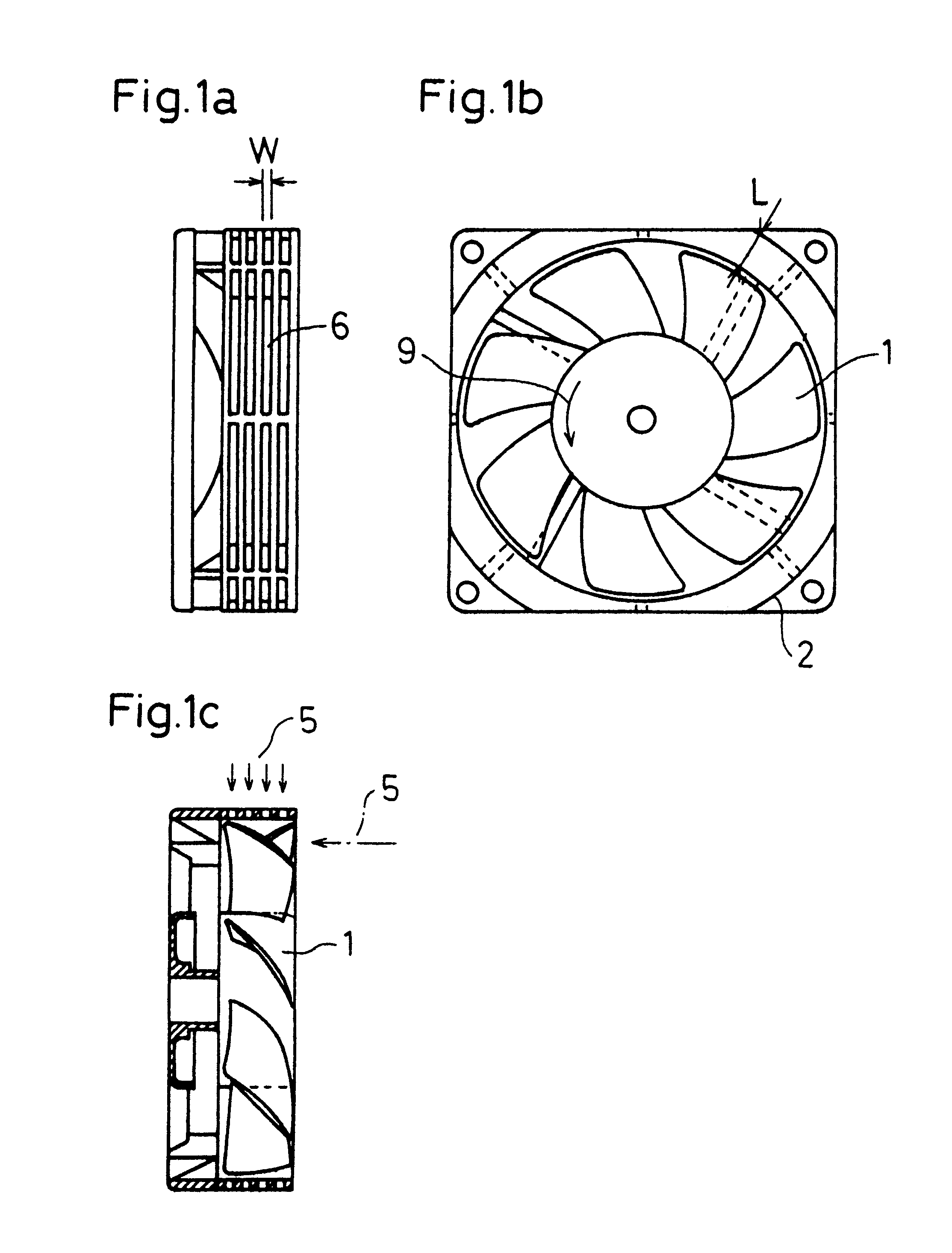
FIGS. 1a, 1b, and 1c show a blower with slits in accordance with the present invention.

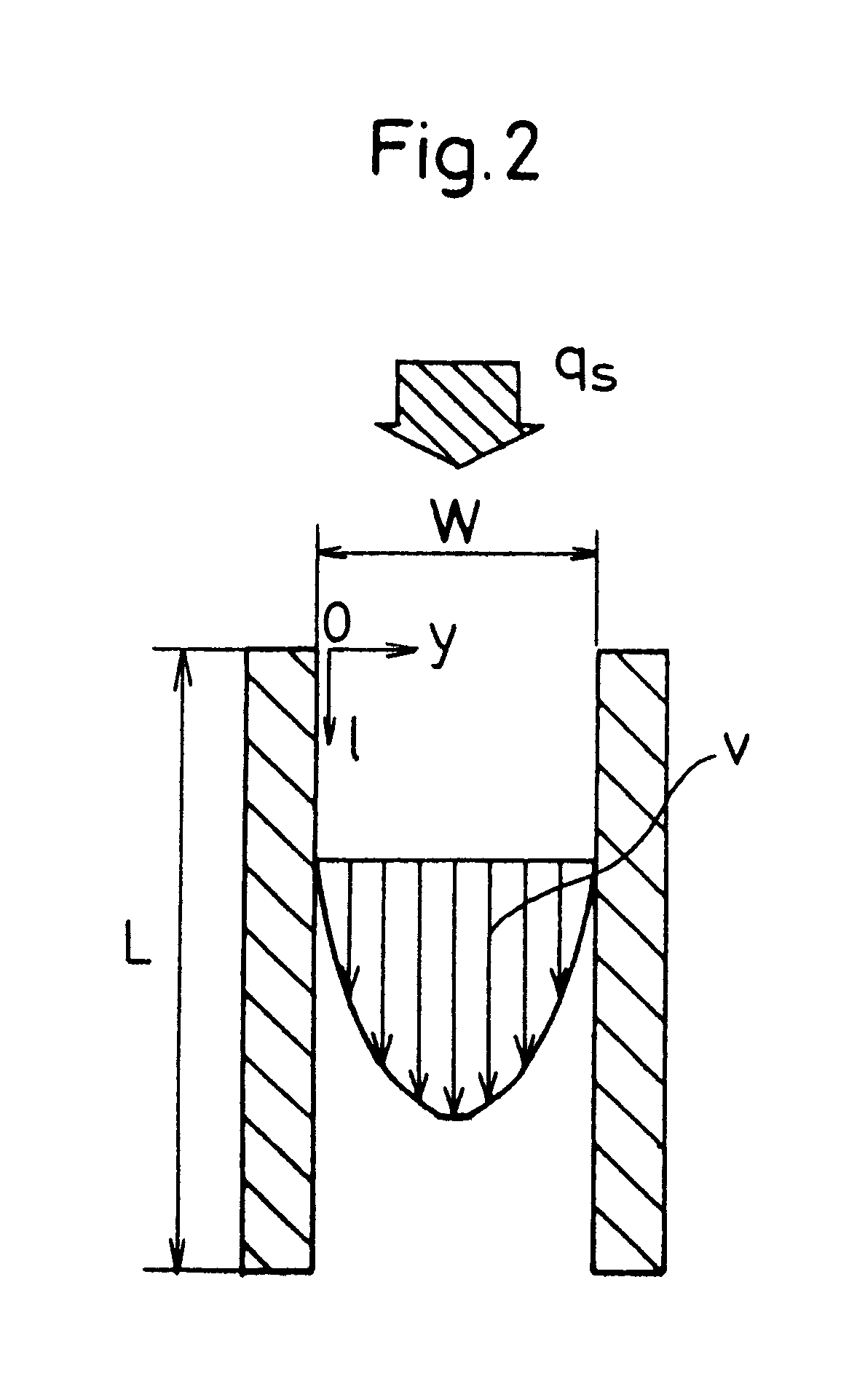
As shown in FIG. 1c, an annular wall 2 is formed with slits 6 for communication between the inner and outer peripheral portions at a portion opposed to the blade tip end of an axial fan 1. Also, the width w of the gap of each of the slits 6 is continuously changed in accordance with a length L in the radial direction of every portion of the annular wall 2 so as to meet the condition wherein the width w of the gap of each of the slits is expressed as follows, where the length in the radial direction of every portion of the annular wall 2 is L, ##EQU3##

to make the inflow resistance at every portion approximately equal over the whole circumference.

A negative pressure is produced on the back pressure side at the blade tip end by rotating the axial fan 1, and by a difference in air pressure between the inner p...


PUM


Abstract

In a blower in which air is sucked to the inside through slits formed in an annular wall, the width w and the number of slits are so set that an air flow of 20 to 40% of the maximum air flow is sucked through the slits in a state in which the static pressure is zero. By this configuration, the fan stall inhibiting effect due to the air flow through the slits and the energy loss due to the viscosity of air yielded in the slits are balanced, whereby the efficiency of the blower can be improved.

Description

The present invention relates to a blower and a method for determining a slit shape for a blower.BACKGROUND OR THE INVENTIONIn recent years, high-density mounting of electrical circuits has been widely used as equipment is miniaturized and becomes electronic. Accordingly, because of the increase in heat density of the electronic equipment, a blower has been used for cooling the equipment.For a conventional blower, as shown in FIG. 9, an annular wall 2 is formed so as to be spaced from the blade tip end of an axial fan 1, and the axial fan 1 rotates around a shaft 4 in a blowing state in which a motor 3 is energized, by which an air flow (air quantity per unit time) 5 directed from the suction side to the discharge side is generated.However, in the aforementioned blowing state, the velocity of the air flow increases on the back pressure side of the blade tip end, and a low-energy zone due to the effect of an inter-blade secondary flow is produced on the blade trailing edge side where...

Claims


Application Information

Patent Timeline
IPC IPC(8): F04D19/00F04D29/40F04D29/54F04D25/08F04D29/66
CPCF04D19/002F04D29/545Y10S415/914F04D25/0613F04D29/526
Inventor FUJINAKA, HIROYASU
Owner PANASONIC CORP
Features
  • Generate Ideas
  • Intellectual Property
  • Life Sciences
  • Materials
  • Tech Scout
  • Unparalleled Data Quality
  • Higher Quality Content
  • 60% Fewer Hallucinations
Learn More