Air bag module with deployment door

a technology of airbags and doors, applied in the direction of vehicular safety arrangments, pedestrian/occupant safety arrangements, vehicle components, etc., can solve the problem that the reaction canister cannot be eliminated, and achieve the effect of reducing the number of reaction canisters

Inactive Publication Date: 2001-02-20
TRW VEHICLE SAFETY SYST
View PDF11 Cites 61 Cited by
  • Summary
  • Abstract
  • Description
  • Claims
  • Application Information

AI Technical Summary

Problems solved by technology

The reaction canister can not be eliminated, however, if it is used to support the deployment door.

Method used


Image

  • Air bag module with deployment door
  • Air bag module with deployment door
  • Air bag module with deployment door

Examples


second embodiment

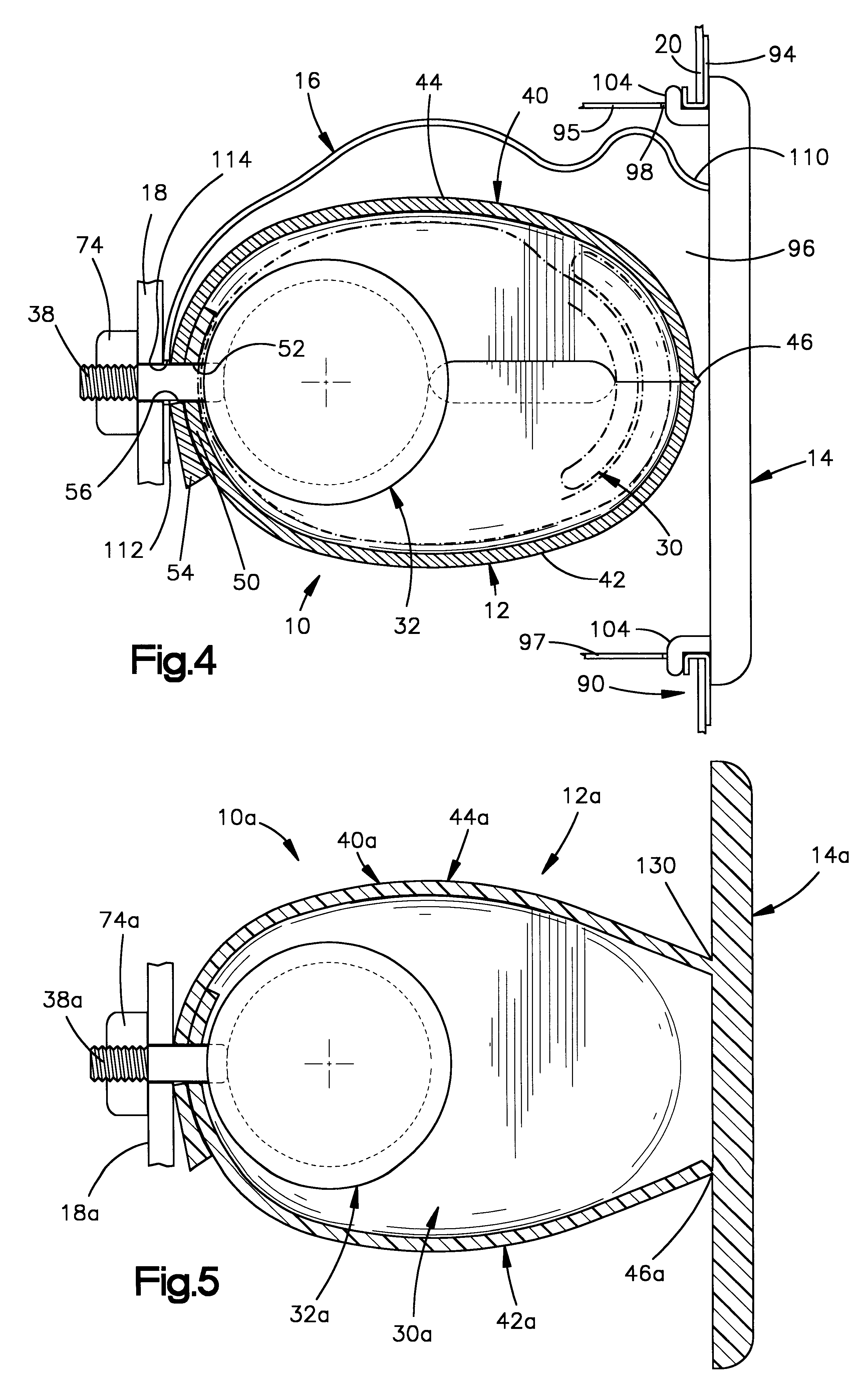
FIG. 5 illustrates a vehicle safety apparatus 10a constructed in accordance with the present invention. The safety apparatus 10a is generally similar in construction and operation to the safety apparatus 10 (FIGS. 1-4), and similar parts are given similar reference numerals with the suffix "a" added for clarity.

In the safety apparatus 10a, the deployment door 14a is molded as one piece with the cover 40a. Specifically, the deployment door 14a is permanently connected with the second cover part 44a at a connection location 130. The deployment door 14 is releasably connected with the first cover part 42a by a rupturable portion or tear seam 46a. The deployment door 14a is still movable relative to the seat frame member 18a, because of the flexibility of the first and second cover parts 42a and 44a.

third embodiment

FIG. 6 is a schematic view of a vehicle safety apparatus 10b which is constructed in accordance with the present invention. The vehicle safety apparatus 10b is mounted in an instrument panel 140 of a vehicle.

The safety apparatus 10b includes an air bag module 12b which is fixed by one or more mounting bolts 38b to a structural portion 142 of the vehicle instrument panel 140. The module 10b includes an inflator assembly 32b and an air bag 30b within a cover 40b. The safety apparatus 10b also includes a deployment door 14b. The deployment door 14b is releasably secured by mounting tabs 144 to an exposed trim portion 146 of the vehicle instrument panel 140, thereby covering a deployment opening 148 in the instrument panel. The deployment door 14b faces generally rearward in the vehicle, so the air bag module 12b is a "mid-mount" type of module.

The safety apparatus 10b includes a flexible tether 16b. A first end portion 110b of the tether 16b is secured by a mounting bolt 38b to the veh...

fourth embodiment

FIG. 7 is a schematic view similar to FIG. 6 of a vehicle safety apparatus 10c which is constructed in accordance with the present invention. In the safety apparatus 10c, the deployment door 14c faces generally upward in the vehicle, so the air bag module 10c is a "top-mount" type of module.

Upon actuation of the inflator assembly 32c and inflation of the air bag 30c, the deployment door 14c is pushed out of engagement with the instrument panel 140c by the inflating air bag. The deployment door 14c moves generally upward in the vehicle. The tether 16c limits movement of the deployment door 14c away from the module 12b beyond a predetermined distance upon inflation of the air bag 30c. Because the deployment door 14c is not rigidly connected to the module 12c or to the structural portion 142c of the instrument panel 140c, the deployment door is positionable on the instrument panel separately from the module during assembly of the vehicle safety apparatus 10c into the instrument panel. ...


PUM


Abstract

A vehicle occupant safety apparatus (10) for mounting in a portion (20) of a vehicle includes a module (12). The module (12) includes an inflatable vehicle occupant protection device (30), an inflation fluid source (32), a cover (40) for the vehicle occupant protection device and the inflation fluid source, and bolts (38) for mounting the module in the vehicle portion. The module cover (40) encloses the inflation fluid source (32) and the protection device (30) when the protection device is in a deflated condition. The module cover (40) is made from a material which is flexible and wrapped around the vehicle occupant protection device (30) and the inflation fluid source (32). The apparatus also includes a deployment door (14), and tabs (90) (104) for releasably mounting the deployment door on the vehicle portion (20) for movement relative to the vehicle portion upon inflation of the protection device (30). The apparatus (10) also includes a flexible tether (16) connecting the deployment door (14) with the module (12) for limiting movement of the deployment door away from the module beyond a predetermined distance upon inflation of the protection device (30).

Description

1. Technical FieldThe present invention relates to a vehicle safety apparatus and, in particular, to an air bag module including a deployment door for covering a deployment opening through which the air bag is inflatable.2. Description of the Prior ArtSome known air bag modules include an air bag which surrounds an inflator to provide the module with a soft or flexible external surface. It is known to position this "soft pack" type of air bag module inside a reaction canister. A deployment door is mounted on the reaction canister to cover the air bag and the inflator. The assembly of the door and the reaction canister with the module inside is then mounted in the vehicle seat. The door preferably has a Class A exterior surface to match the seat covering material. Upon actuation of the inflator, the inflating air bag pushes open the deployment door. The reaction canister directs the flow of inflation fluid into the air bag.If a diffuser is incorporated in the soft pack module, the ne...

Claims


Application Information

Patent Timeline
Patent Type & Authority Patents(United States)
IPC IPC(8): B60R21/20B60R21/207B60R21/215B60R21/216B60R21/217
CPCB60R21/207B60R21/216B60R21/215B60R21/2176
Inventor BOWERS, PAUL A.SUTHERLAND, DANIEL R.
Owner TRW VEHICLE SAFETY SYST
Why Eureka
Try Eureka