Hair styling tongs with biased handles

a technology of hair styling and tongs, which is applied in the field of hairdressing tongs, can solve the problems of not being able to achieve all the desired shaping effects and being difficult to adapt to different types of hair

Inactive Publication Date: 2001-02-20
CONAIR CORP
View PDF10 Cites 67 Cited by
  • Summary
  • Abstract
  • Description
  • Claims
  • Application Information

AI Technical Summary

Benefits of technology

By holding, with the hand, the rear face of the arms in a completely pushed-in position and by pushing the front face of these arms in gradually, the tongs are closed in the conventional, that is to say angular, manner. However, it is possible to press in an identical manner on the front and rear faces of the arms of the handle, in this case closing the pads in a

Problems solved by technology

This type of angular-opening tongs has the fundamental disadvantage that it cannot easily be adapted to different types of hair and in particular, with a constant l

Method used


Image

  • Hair styling tongs with biased handles
  • Hair styling tongs with biased handles
  • Hair styling tongs with biased handles

Examples


Embodiment Construction

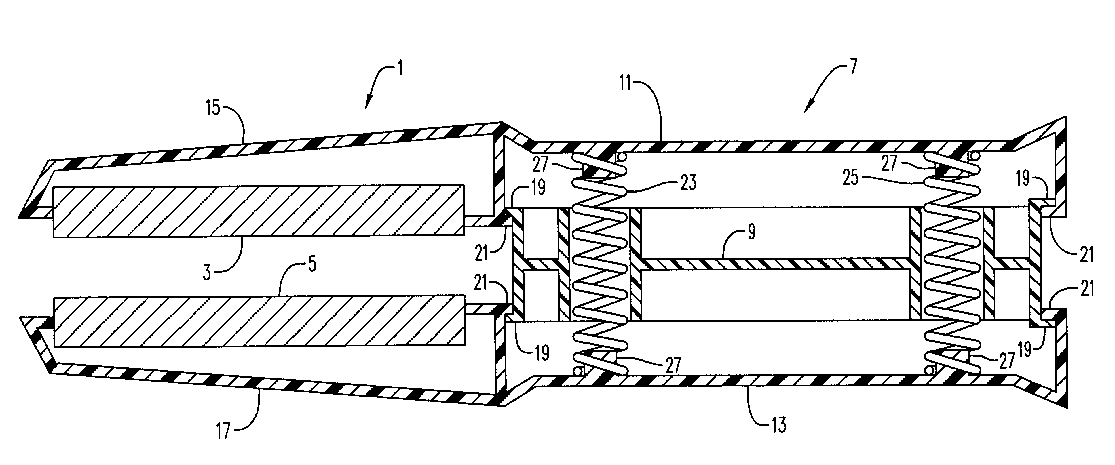
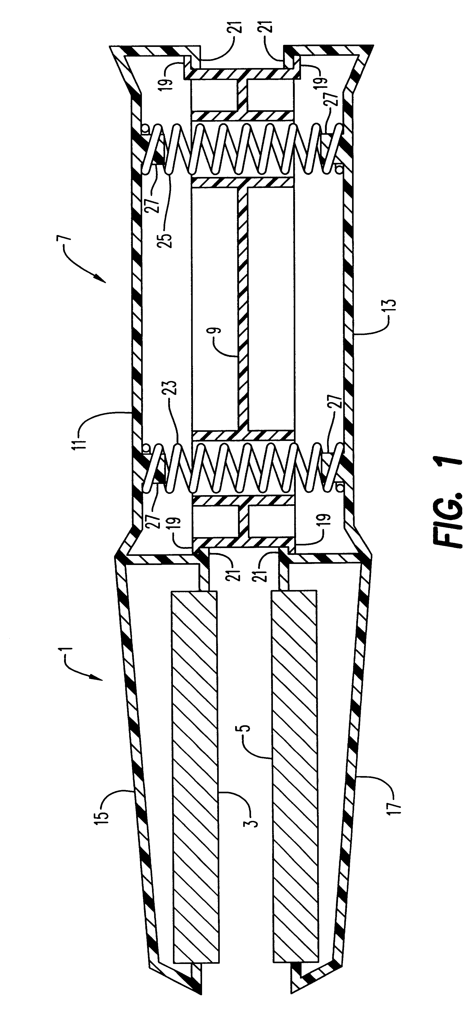
The hairdressing tongs shown by the general reference 1 comprise two heating pads 3 and 5 connected to a handle 7. Handle 7 is made of molded plastic materials. These pads are provided with electric resistors (not shown) fed by an electric wire running through the handle 7. Heating pads 3 and 5 are made of heat conductive materials such as, but not limited to, metallic materials and ceramic materials. This handle 7 consists of a central element 9 and two arms 11 and 13.

The arm 11 extends in a nose 15 in which the heating pad 3 is mounted while the arm 13 extends in a nose 17 in which the heating pad 5 is mounted.

The central element 9 comprises stops 19 at its ends for steps 21 formed on the arms 11 and 13.

The springs 23 and 25, at the front and rear end respectively of the handle 7, are held by studs 27 and separate the arms 11 and 13, and consequently also the heating pads 3 and 5, from one another.

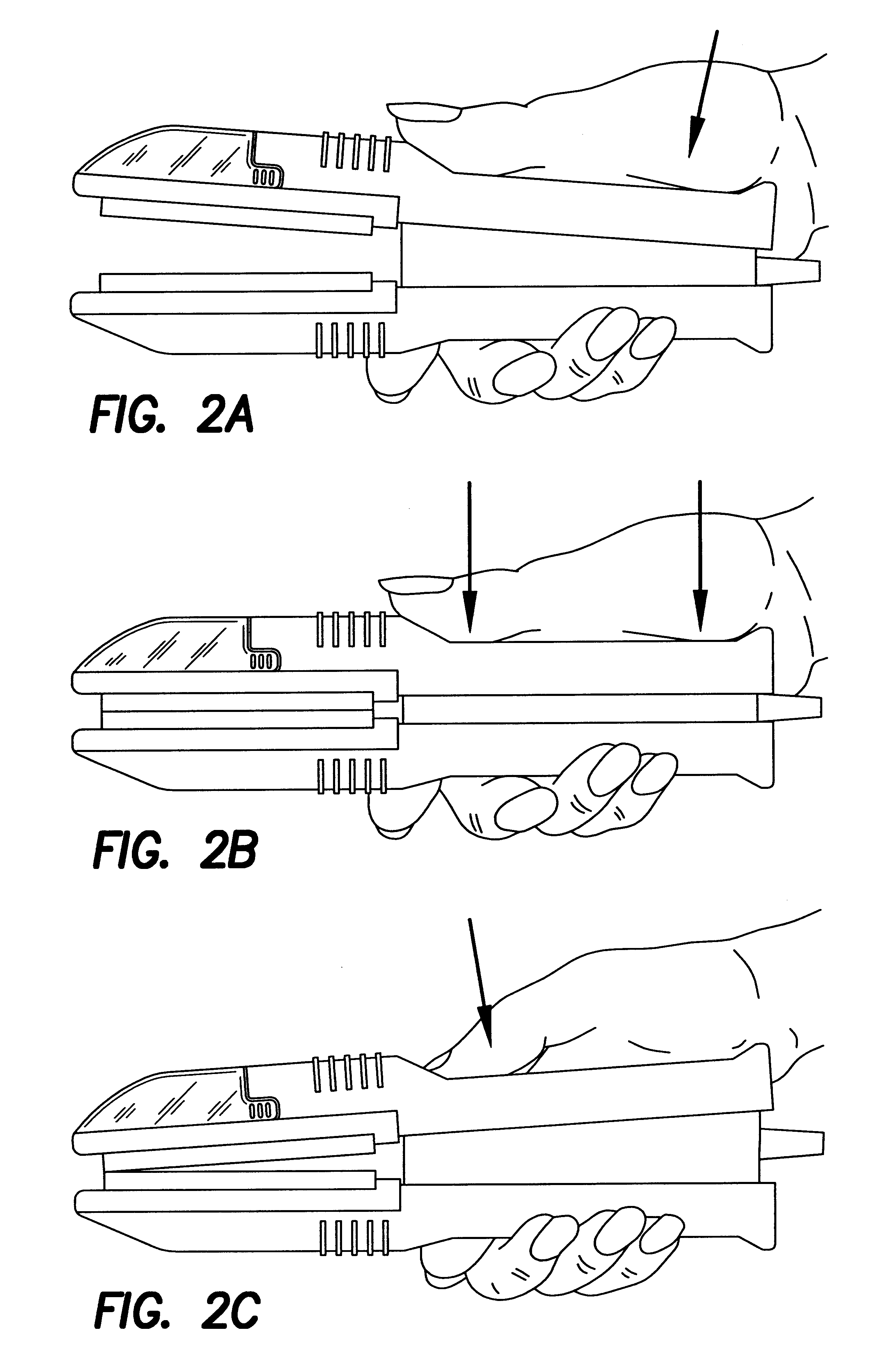
It is easy to see that by pressing (see FIG. 2A) on the rear of the tongs evenly, on...


PUM


Abstract

Hairdressing tongs have a pair of arms extending from handles. Each arm has a heating pad affixed thereto. The handles have opposed openings. A central element is positioned between the handles and fitted within the openings such that the central element is slidable toward the handles. The central element has guide openings. Springs are positioned in the guide openings for biasing apart the handles. The springs enable hand pressure to move the handles and arms together from a completely open position to a completely closed position and, in absence of the hand pressure, to maintain the handles and arms in relatively parallel configuration, biased against stops of the central element.

Description

SUBJECT OF THE INVENTIONThe invention relates to hairdressing tongs for straightening / styling.TECHNICAL BACKGROUNDHairdressing tongs which consist of two heating pads and can be equipped with a water reservoir for simultaneous emission of steam have already been offered on the market. The pads, fixed to the end of two handle arms connected by a pivot and a spring, hold the two arms apart from one another in the rest position.By acting on the handle using the hand, it is possible, starting from a position of maximum opening, to move the two arms, and therefore the pads which are integral therewith, towards one another through a variable acute angle to, at the end of travel, bring the pads into contact and in principle into a parallel position.Locks of hair are gripped between the heating pads and the hair can thus be smoothed by making it slide between the hot pads, if necessary with an emission of steam obtained from water originating from a reservoir incorporated in the support of ...

Claims


Application Information

Patent Timeline
IPC IPC(8): A45D2/00A45D2/04
CPCA45D2/001A45D2001/008A45D2/00
Inventor SMAL, HENRI
Owner CONAIR CORP
Why Eureka
Try Eureka