Bottle rack system

a bottle rack and bottle technology, applied in the direction of machine supports, liquid handling, washstands, etc., can solve the problems of time-consuming and frustrating to dispense the contents of a direct dispense bottle rack

Inactive Publication Date: 2001-04-24
FALOR BRIAN K
View PDF16 Cites 30 Cited by
  • Summary
  • Abstract
  • Description
  • Claims
  • Application Information

AI Technical Summary

Benefits of technology

FIG. 3A is a side plan view showing the two side edges of the slide-in drip tray inserted into and held within the drip tray insertion channels of the paralle

Problems solved by technology

It is often time consuming and frustrating to dispense the contents of a direct dispen

Method used


Image

  • Bottle rack system
  • Bottle rack system
  • Bottle rack system

Examples


Embodiment Construction

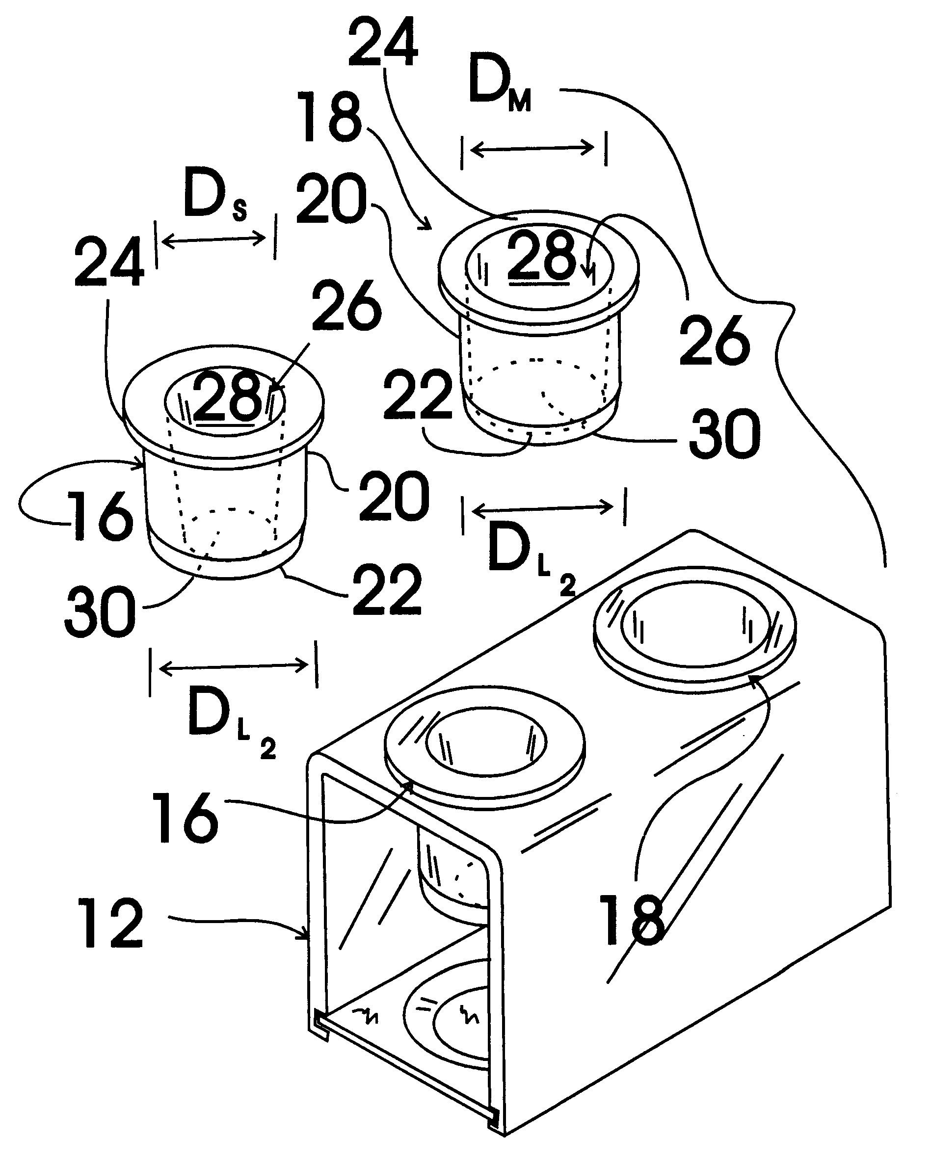
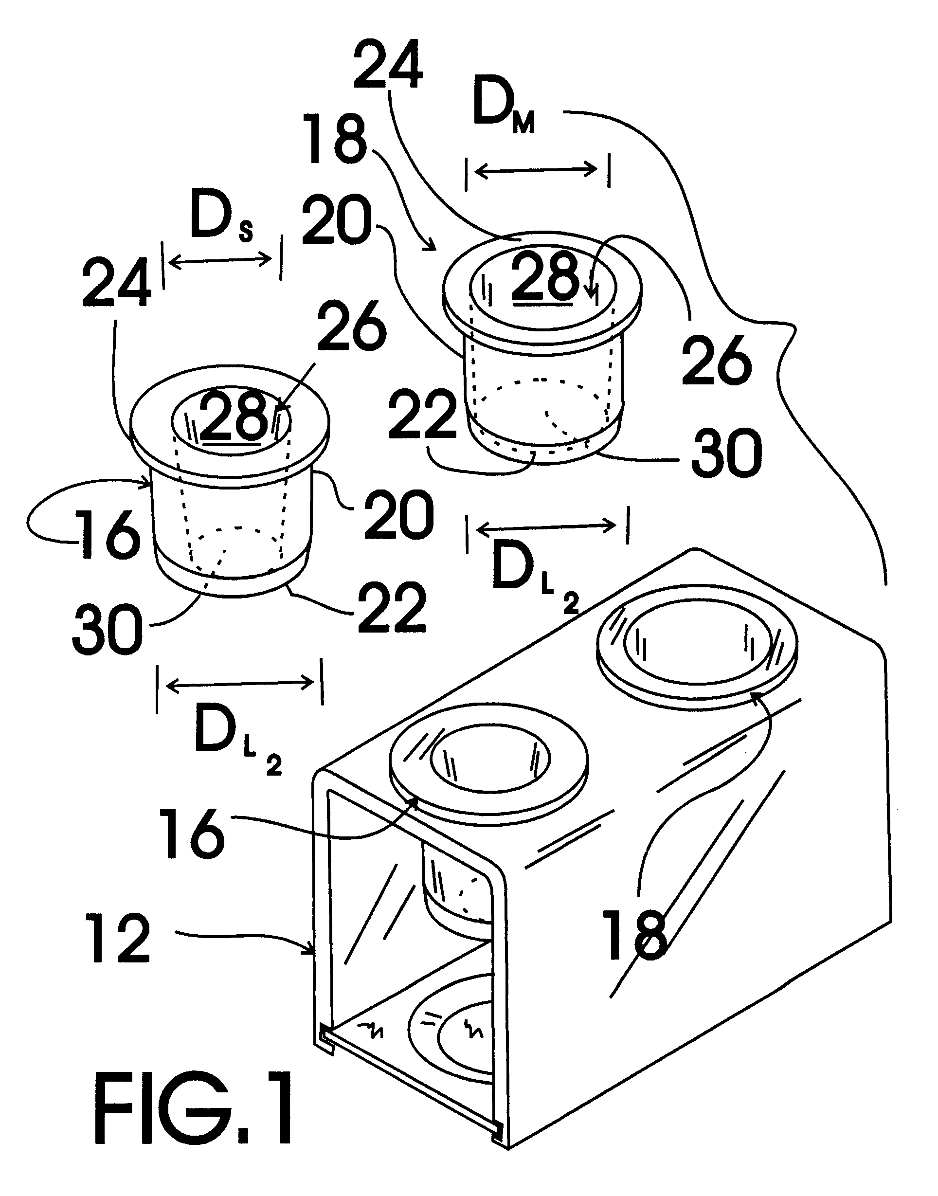
FIG. 1 shows an exemplary embodiment of the bottle rack system of the present invention generally designated 10. Bottle rack system 10 includes a U-shaped bent plastic bottle support member, generally designated 12; a slide-in drip tray, generally designated 14; two identical small diameter neck inserts, each generally designated 16; and two identical medium diameter neck inserts, generally designated 18. Each of the small and medium diameter neck inserts 16,18 is formed from a resilient plastic and includes a center portion 20, a tapered insertion tip 22, a support member contact flange 24 and a tapered bottle neck insertion passageway 26 that tapers in diameter from a larger diameter cap insertion opening 28 to a smaller diameter cap exit opening 30 (shown in dashed lines).

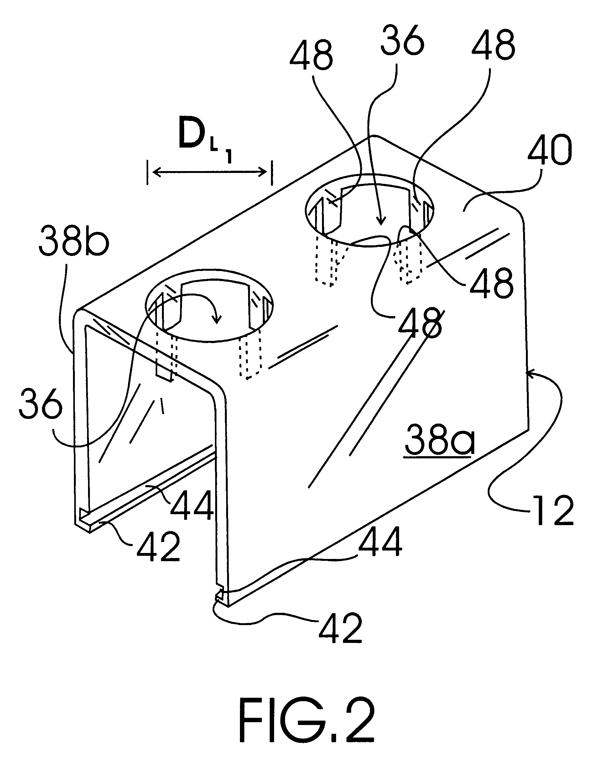
FIG. 2 shows U-shaped bent plastic bottle support member 12 in isolation with the small and medium diameter neck inserts 16,18 (FIG. 1) removed from the two circular neck openings 36. U-shaped bent plastic bottl...


PUM


Abstract

A bottle rack system for storing direct dispense bottles, such as used to store and dispense ketchup, salad dressing, steak sauce, etc., in an inverted position with the bottle cap positioned below the bottle bottom so that the contents of the bottle accumulate adjacent to the dispensing opening of the direct dispense bottle so as to be readily available for dispensing. The bottle rack system includes a bottle support member, a slide-in drip tray, two small diameter neck inserts, and two medium diameter neck inserts.

Description

The present invention relates to bottle storage shelves and more particularly to a bottle rack system for storing direct dispense bottles, such as used to store and dispense ketchup, salad dressing, steak sauce, etc., in an inverted position with the bottle cap positioned below the bottle bottom so that the contents of the bottle accumulate adjacent to the dispensing opening of the direct dispense bottle so as to be readily available for dispensing; the bottle rack system including a bottle support member, a slide-in drip tray, two small diameter neck inserts, and two medium diameter neck inserts; the bottle support member being U-shaped and including a pair of parallel oriented end portions connected by a perpendicularly oriented middle portion; an inner bottom edge of each of the parallel oriented end portions having a drip tray insertion channel formed along the length thereof sized to receive and hold an edge of the slide-in drip tray; the middle portion having two circular bott...

Claims


Application Information

Patent Timeline
IPC IPC(8): A47G23/00A47G23/02B67D3/00B67C9/00
CPCA47G23/0241B67C9/00B67D3/0029
Inventor FALOR, BRIAN K.
Owner FALOR BRIAN K
Why Eureka
Try Eureka