Grinding body for on-line roll grinding

a rolling ball and rolling ball technology, applied in the direction of gear teeth, manufacturing tools, manufacturing apparatus, etc., can solve the problems of uneven contact between the grinding stone and the rolling ball, unusable rolling, and limited oscillating speed and grinding for

Inactive Publication Date: 2001-04-24
MITSUBISHI HITACHI METALS MASCH INC +2
View PDF12 Cites 22 Cited by
  • Summary
  • Abstract
  • Description
  • Claims
  • Application Information

AI Technical Summary

Problems solved by technology

Eventually, the roll becomes unusable.
(1) Vibrations occurring in the grinding body 22 during grinding include resonance vibrations associated with vibrations of the roll 21, and self-excited vibrations associated with stick-slips at the interface between the grindstone and the roll 21 in contact with each other. The self-excited vibrations occur because of the low dynamic stiffness of the support member for the grindstone, i.e., the circular base plate. The self-excited vibrations lead to the formation of the pitching surface mark 23.
(2) Since the support member for the grindstone is a flexible, thin, circular base plate, uneven contact of the grindstone with the roll is liable to occur, under a high grinding force, according to changes in roll setting. Thus, the oscillating speed and the grinding force are restricted, so that the grinding power declines.
(3) If the thickness of the abrasive grain layer secured to the thin circular base plate differs, the rigidity of the grindstone also varies. FIG. 13 is a graph showing the relationship between the thickness of a grindstone and the rigidity of the grindstone. As a one-dot chain line in the drawing indicates, decreases in the grindstone thickness result in rapid decreases in the grindstone rigidity. Thus, the accuracy of grinding lowers according to changes in the rigidity of the grindstone.
Thus, the life of the grindstone shortens.
(4) When the grindstone supported on the flexible thin circular base plate is pressed against the roll with a predetermined pressing force, local warpage occurs, and the stress of the grindstone at the site of warpage increases.
Since the thickness of the abrasive grain layer is thus restricted, the life of the grindstone becomes short.
However, the pitching surface mark associated with self-excited vibrations, the problem with the earlier technology I, has not been resolved.
However, its diminution has not been complete.

Method used


Image

  • Grinding body for on-line roll grinding
  • Grinding body for on-line roll grinding
  • Grinding body for on-line roll grinding

Examples


first embodiment

[First Embodiment]

Constitution

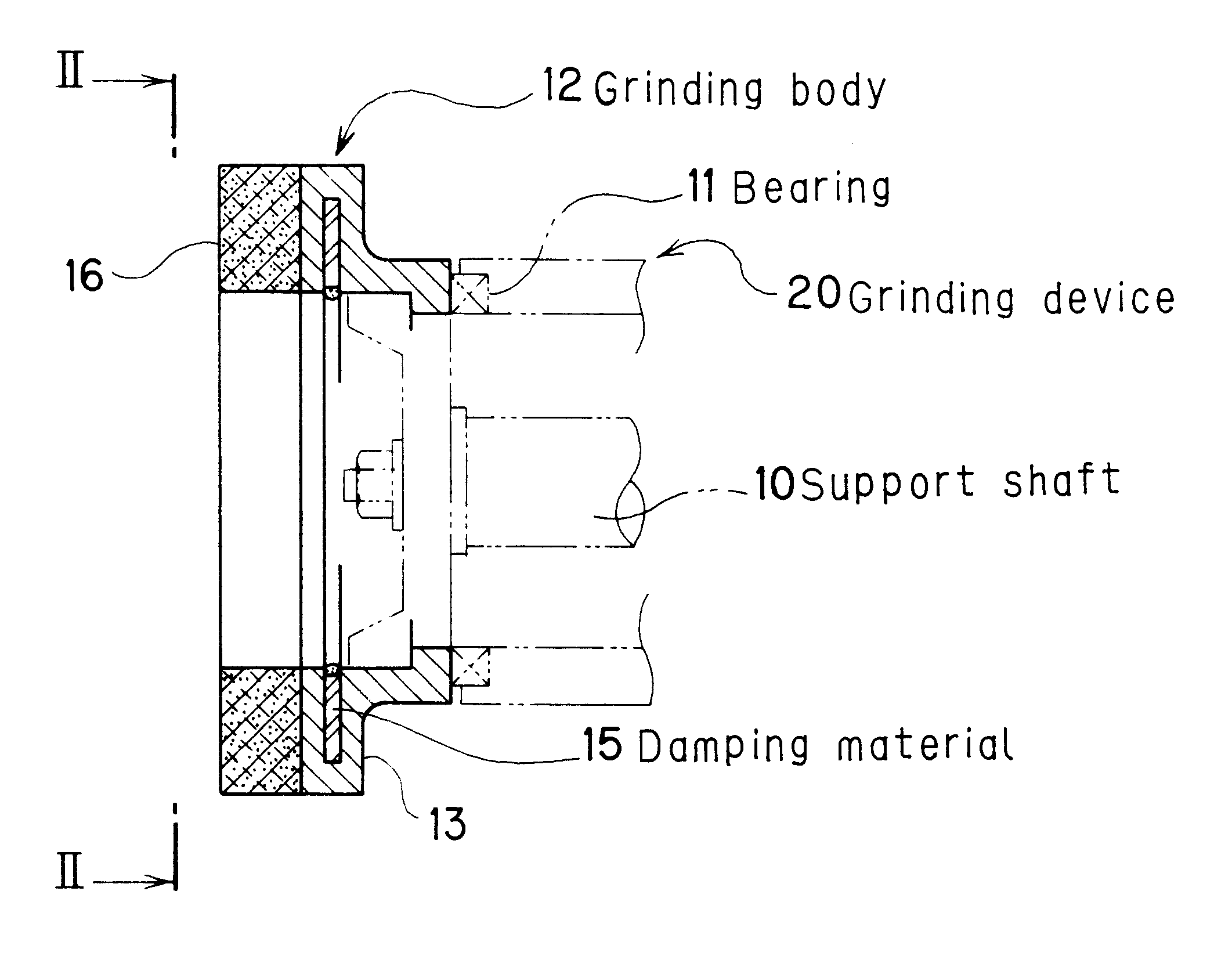
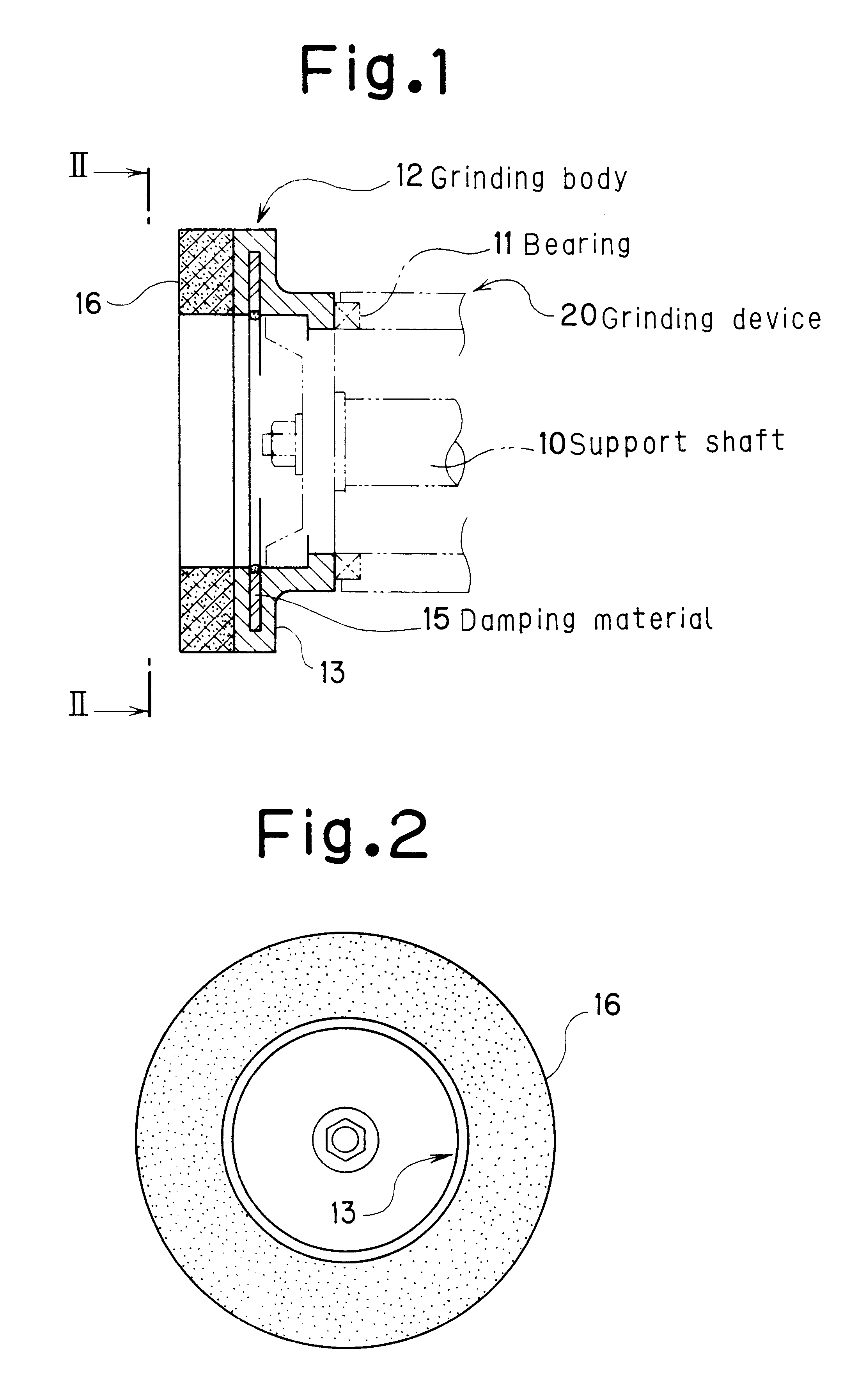
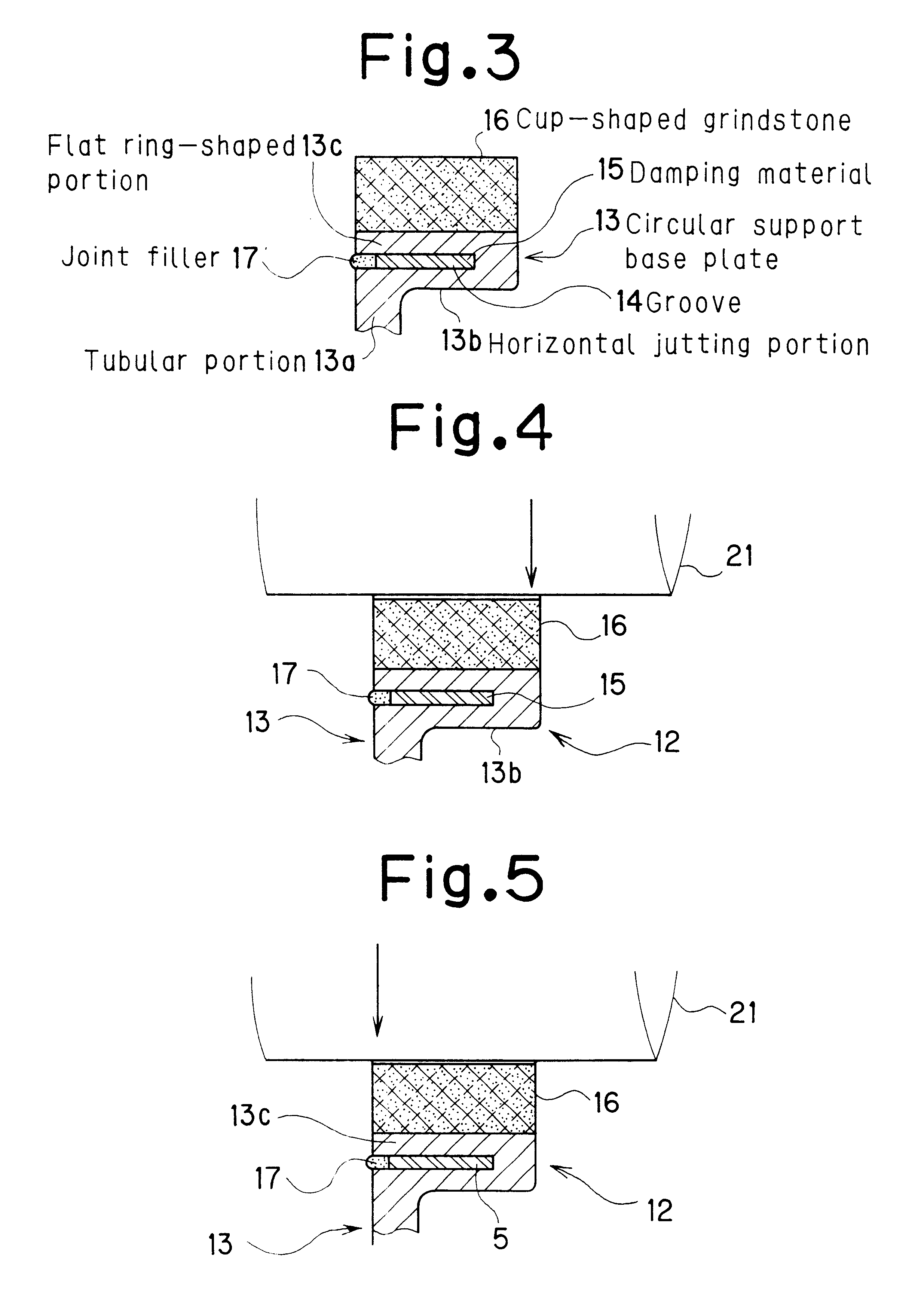
In FIGS. 1 to 3, the reference numeral 12 denotes a grinding body having a central portion and a peripheral edge portion rotatably supported by a support shaft 10 and a bearing 11 of an on-line roll grinding device 20. The grinding body 12 is composed of a circular support base plate 13 of a metal, such as SUS, constructed in a two-layer structure from a horizontal jutting portion 13b and a flat ring-shaped portion 13c, the horizontal jutting portion 13b jutting outward from a short tubular portion 13a, and the flat ring-shaped portion 13c extending upward and then toward a central side from an outer peripheral edge portion of the horizontal jutting portion 13b in such a manner as to be opposed to the horizontal jutting portion 13b while defining a transverse groove 14 opening toward the central side; a damping material 15 filled into the groove 14; and an integral, cup-shaped grindstone 16 secured onto a surface of the flat ring-shaped portion 13c. The...

second embodiment

[Second Embodiment]

Constitution

This embodiment is the preceding First Embodiment, but with the constitution of the circular support base plate 13 being partially changed such that the plate thickness b of the horizontal jutting portion 13b and the plate thickness c of the flat ring-shaped portion 13c will be in the relationship b

In FIGS. 9 to 10, dimensions for the plate thickness in the circular support base plate 13 are set such that the plate thickness c of the flat ring-shaped portion 13c is greater than the plate thickness b of the horizontal jutting portion 13b, i.e., b

A...


PUM

PropertyMeasurementUnit
angleaaaaaaaaaa
forceaaaaaaaaaa
thicknessaaaaaaaaaa

Abstract

A grinding body for on-line roll grinding has a grindstone of a cup shape. The grindstone is on a surface portion, and near a peripheral edge, of a circular support base plate, so that a peripheral edge portion of the circular support base plate has on a surface side thereof a two-layer structure. This two-layered structure includes a flat ring-shaped portion jutting toward an inner periphery so as to define a groove opening inward. The grindstone is mounted on the flat ring-shaped portion; and a damping material is filled and mounted into the groove. This grinding body can effectively prevent the formation of a spiral mark and a pitching surface mark, improve the grinding power and grinding accuracy, and prolong the life of the grindstone.

Description

1. Field of the InventionThe present invention relates to a grinding body for an on-line roll grinding device which is mounted and used on a rolling mill.2. Description of the Related ArtWhen on-line roll grinding is performed, it is common practice, as shown in FIG. 16, that a plurality of on-line roll grinding devices 20 are placed to face a roll 21 to be ground, each of the on-line roll grinding devices 20 having a grinding body 22 capable of reciprocating in an axial direction of the roll 21 and rotatable along the axial direction, and the grinding body 22 is pressed against a surface of the roll 21, which is rotating, to grind the surface of the roll 21. A shaft center 20a of the grinding device 20 is set at the same height as an axis 21a of the roll 21, or at a height displaced upward or downward (an offset height H) by a certain distance from the axis 21a. The shaft center 20a of the grinding device 20 is also set to be horizontally inclined at an angle of .alpha. (e.g., 0.5....

Claims


Application Information

Patent Timeline
Patent Type & Authority Patents(United States)
IPC IPC(8): B24D7/02B24D7/00B24D7/18B24B5/16B24B5/00B21B28/00B21B28/04B24B5/37
CPCB24B5/16B24D7/02B24D7/18B21B28/04B24B5/00
Inventor HAYASHI, KANJISUZUKI, MAKOTOKATAGIRI, HIROSHI
Owner MITSUBISHI HITACHI METALS MASCH INC
Why Eureka
Try Eureka