
Method of making a read head with high resistance soft magnetic flux guide layer for enhancing read sensor efficiency

a technology of soft magnetic flux and read sensor, which is applied in the field of high resistance soft magnetic flux guide layer read head, can solve the problems of unstable magnetic spin in the end portion affecting the performance of the free film, and changing the magnetics of the free film

Inactive Publication Date: 2001-05-01
IBM CORP
View PDF32 Cites 49 Cited by
  • Summary
  • Abstract
  • Description
  • Claims
  • Application Information

AI Technical Summary

Benefits of technology

We have also provided several methods of making the one or more flux guide layers. In one method the width of the one or more flux guide layers is greater than the width (track width) of the read sensor. In another method the width of the one or more flux guide layers and the read sensor layer are the same. This latter method gives better control over the dimensions of the one or more flux guides in order to optimize resistivity and saturation magnetization of the one or more flux guide layers.

Problems solved by technology

Unfortunately, magnetic spins in end portions of the free film are unstable.
This changes the magnetics of the free film and affects its performance.
Unfortunately, upon the occurrence of a flux incursion from a rotating magnetic disk the field in the read sensor decays from a maximum at the ABS to zero at its back edge (stripe height).
This decay reduces the ratio of the read sensor so that it is less efficient.
Unfortunately, this small amount of insulation seriously impacts a necessary magnetic path between the read sensor and the flux guide layer.
For this reason flux guides have not been effective and therefore they have not been employed.

Method used


Image

  • Method of making a read head with high resistance soft magnetic flux guide layer for enhancing read sensor efficiency
  • Method of making a read head with high resistance soft magnetic flux guide layer for enhancing read sensor efficiency
  • Method of making a read head with high resistance soft magnetic flux guide layer for enhancing read sensor efficiency

Examples


Embodiment Construction

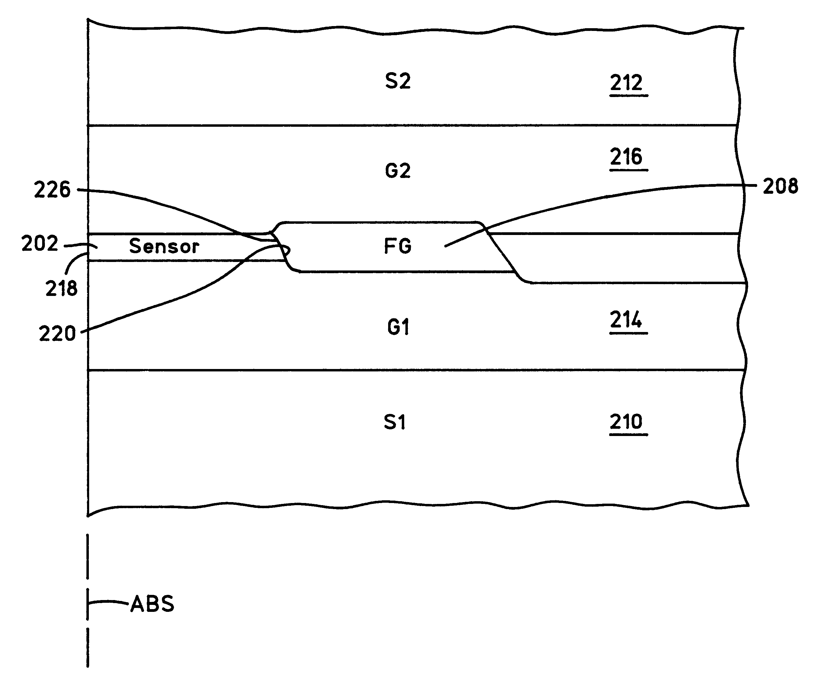
FIGS. 9-12 illustrate a first embodiment of the present invention 200. FIG. 9 shows a schematic illustration of a read sensor 202, first and second high conductance lead layers 204 and 206 and a flux guide 208. The read sensor 202 may be either an anisotropic magnetoresistive (AMR) or a spin valve sensor as desired. In FIGS. 10-12 first and second shield layers 210 and 212 and first and second read gap layers 214 and 216 are added to the cross-sections taken in FIG. 9. As can be seen from FIGS. 10-12 the read sensor 202, the first and second leads 204 and 206 and the flux guide 208 are sandwiched between the first and second read gap layers 214 and 216 and the first and second read gap layers 214 and 216 are sandwiched between the first and second shield layers 210 and 212. As shown in FIGS. 11 and 12 the first and second leads 204 and 206 are a combination of hard bias (HB) and conductive lead material which are discrete films (not shown).

As shown in FIG. 9 the read sensor 202 has ...


PUM

PropertyMeasurementUnit
Fractionaaaaaaaaaa
Fractionaaaaaaaaaa
Fractionaaaaaaaaaa

Abstract

A read head has a flux guide layer that is immediately adjacent (abuts) the back edge of a read sensor. The flux guide layer is made of a high resistance soft magnetic material that conducts magnetic flux from the back edge of the read sensor so that the magnetic response at the back edge of the read sensor is significantly higher than zero. This increases the efficiency of the read sensor. The material for the flux guide layer is A-B-C where A is selected from the group Fe and Co, B is selected from the group Hf, Y, Ta and Zr and C is selected from the group O and N. In a preferred embodiment A-B-C is Fe-Hf-O and the Msrho of the flux guide layer is greater than 50 times the Msrho of the read sensor layer where the read sensor layer is NiFe, Ms is saturation magnetization and rho is resistivity. Because of the flux guides high resistance current shunting losses are nearly eliminated.

Description

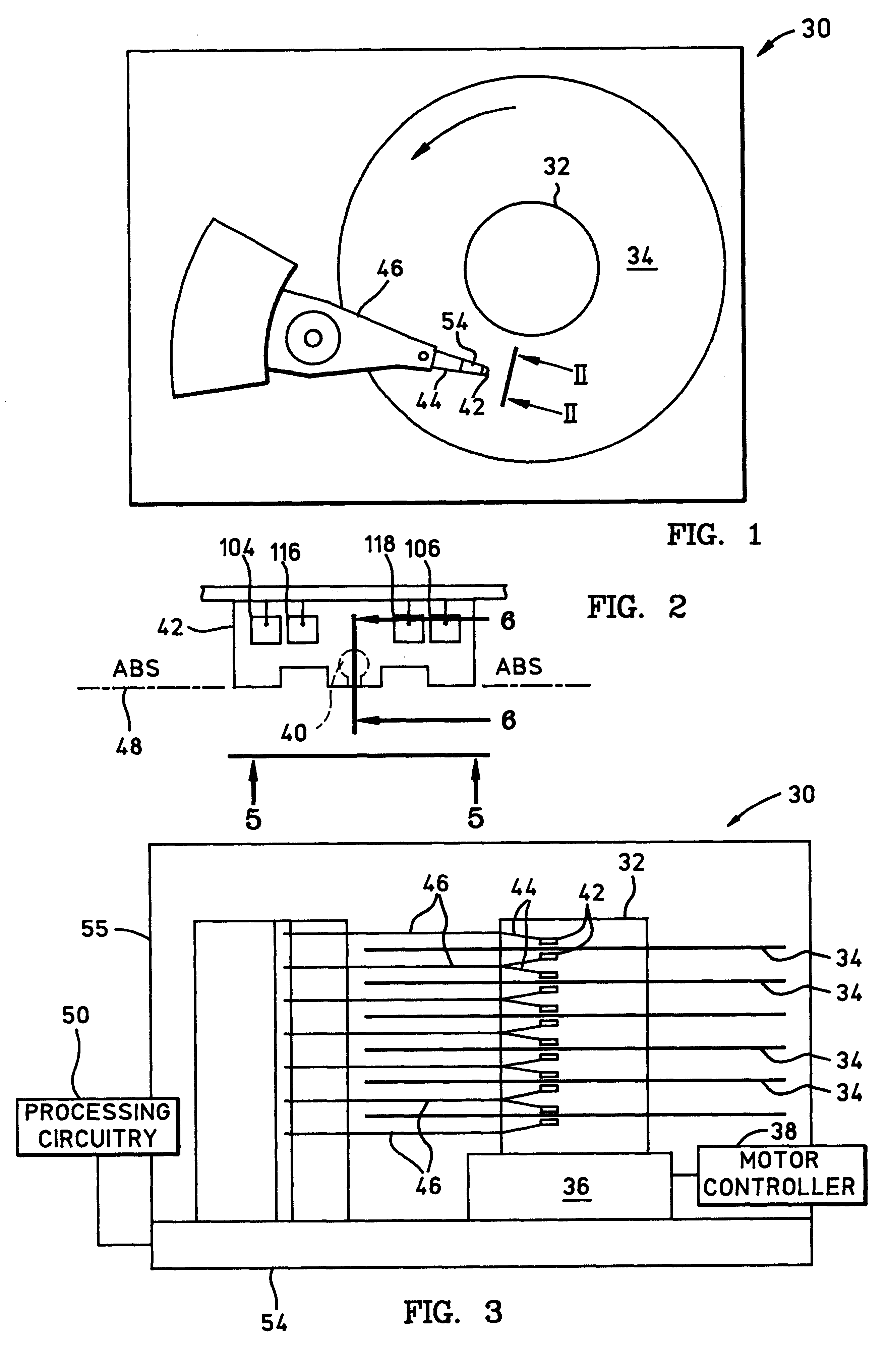
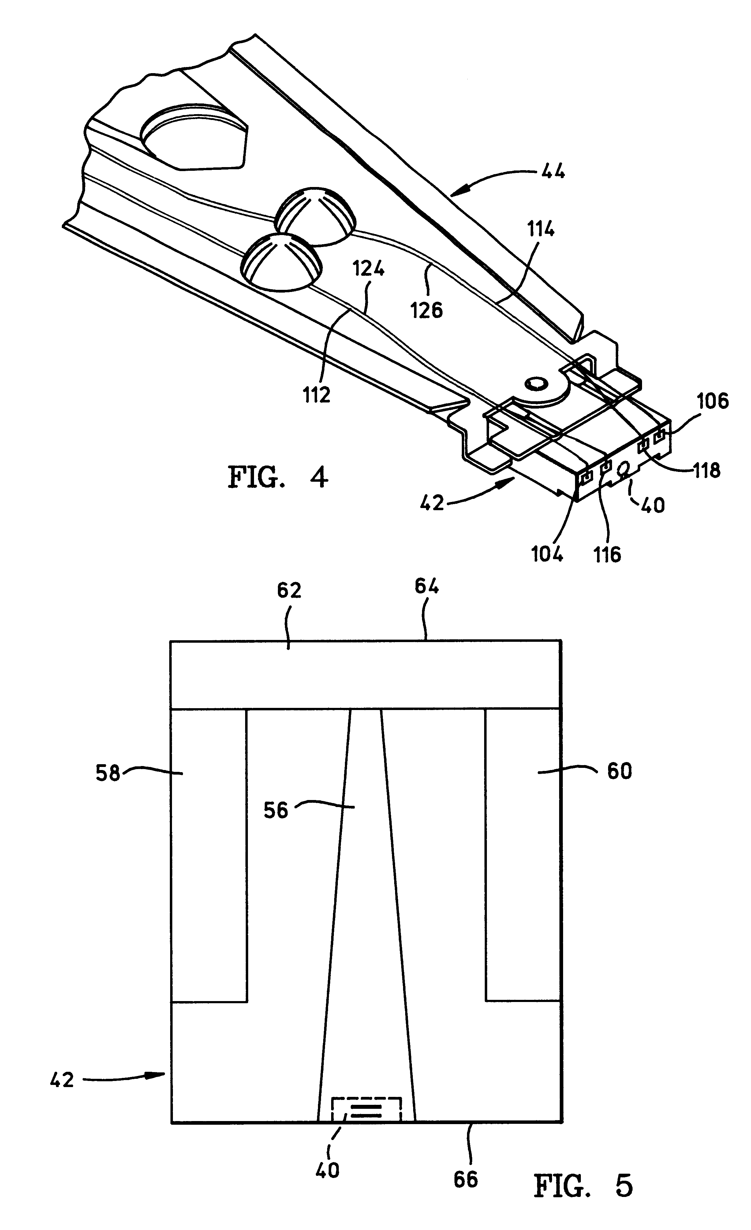
1. Field of the InventionThe present invention relates to a read head with a high resistance soft magnetic flux guide layer for enhancing read sensor efficiency and, more particularly, to one or more high resistance soft magnetic flux guide layers that abut one or more end edges of the read sensor layer for increasing the magnetoresistive signal and / or for protecting the read sensor layer from direct exposure to the environment.2. Description of Related ArtThe heart of a computer is an assembly that is referred to as a magnetic disk drive. The magnetic disk drive includes a rotating magnetic disk, write and read heads that are suspended by a suspension arm above the rotating disk and an actuator that swings the suspension arm to place the read and write heads over selected circular tracks on the rotating disk. The read and write heads are directly mounted on a slider that has an air bearing surface (ABS). The suspension arm biases the slider into contact with the surface of the disk...

Claims


Application Information

Patent Timeline
IPC IPC(8): G11B5/31G11B5/39
CPCB82Y10/00G11B5/3109G11B5/3967G11B5/3919Y10T29/49046Y10T29/49044
Inventor LEE, WEN YAUNGLIN, TSANNMAURI, DANIELESEAGLE, DAVID JOHN
Owner IBM CORP
Learn More