Method and apparatus for telescoping boom with hydraulic extension actuators

a technology of hydraulic extension actuator and telescopic boom, which is applied in the direction of lifting devices, cranes, etc., can solve the problem that conventional lifts do not have rigidly mounted hydraulic actuators

Inactive Publication Date: 2001-06-12
ELLIOTT EQUIP
View PDF2 Cites 34 Cited by
  • Summary
  • Abstract
  • Description
  • Claims
  • Application Information

AI Technical Summary

Problems solved by technology

However, it is not believed that any of these devices use an individual hydraulic actuator for each moving section, such lifts instead conventionally using chains, cables, or the like in pulley systems to achieve the extension and retraction of the boom sections.
Nor do conventional lifts have rigidly mounted hydraulic actuators or sliding supports on the hydraulic actuator piston rods.
No chains, cables or other devices are used to allow one hydraulic actuator to extend or retract more than one section.

Method used


Image

  • Method and apparatus for telescoping boom with hydraulic extension actuators
  • Method and apparatus for telescoping boom with hydraulic extension actuators
  • Method and apparatus for telescoping boom with hydraulic extension actuators

Examples


Embodiment Construction

)

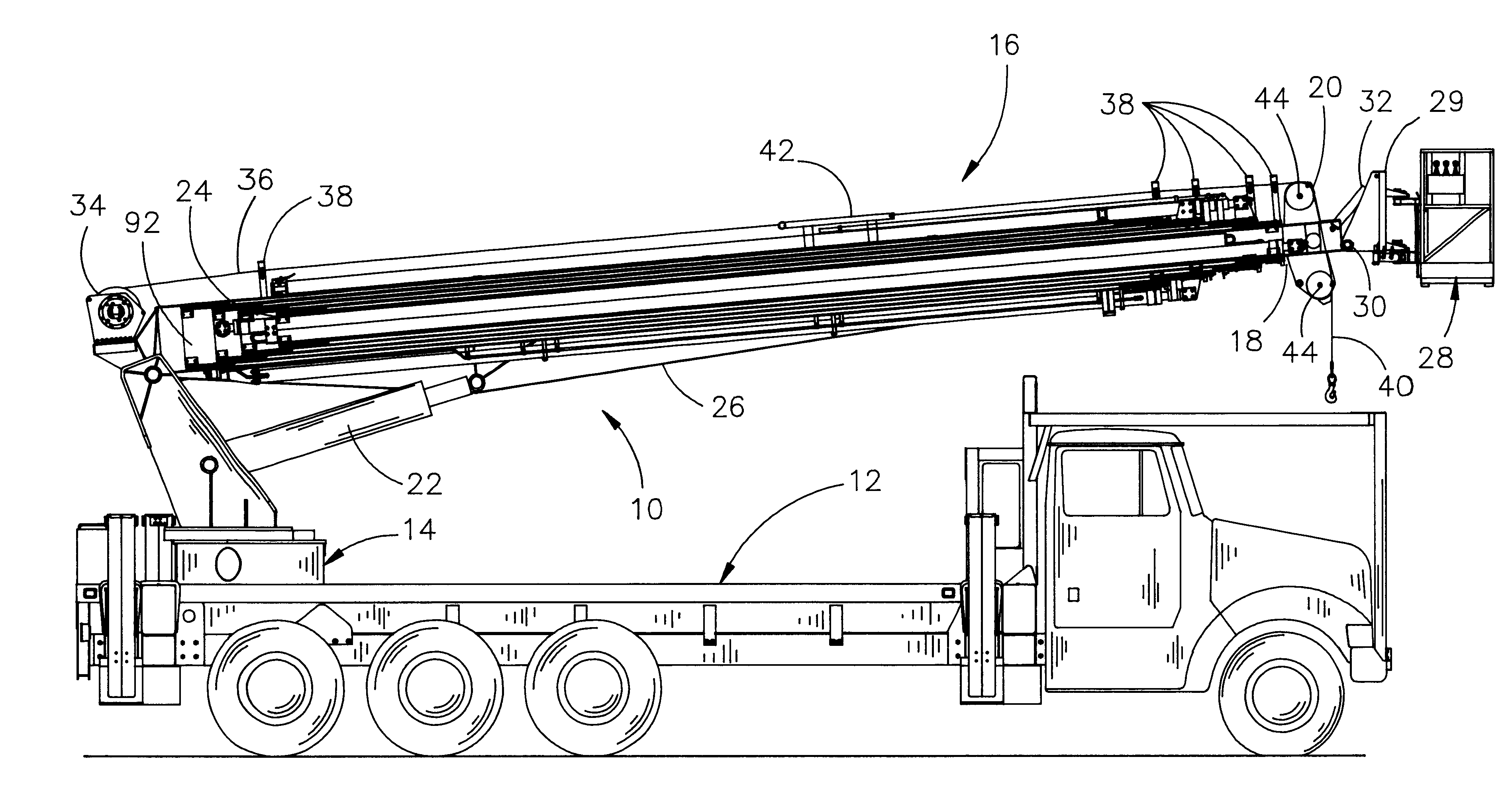
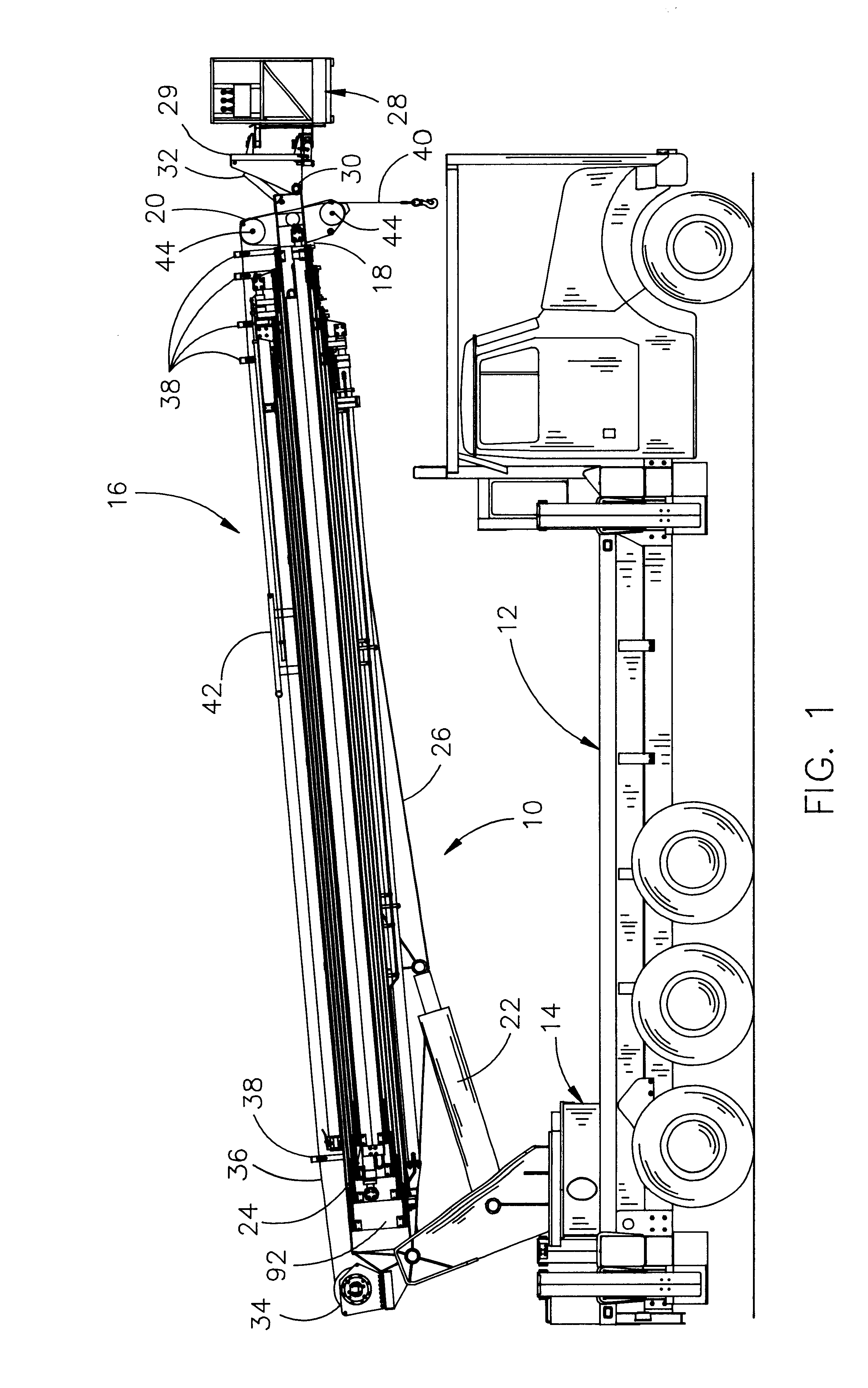
With reference to the Drawings wherein like numerals represent like parts throughout the Figures, an aerial lift apparatus constructed in accordance with the method of the present invention is generally designated by numeral 10 in FIG. 1. Aerial lift 10 may be mounted on a trailer vehicle or self-propelled vehicle such as a truck 12 or the like by a rotatable pedestal 14. Lift 10 is generally used for lifting a person vertically and / or moving the person laterally and for that reason, the use of "upper" and "outer" in this description means in the direction away from the pedestal 14 and the use of one of said terms does not negate or exclude the applicability of the other. For the sake of clarity of description, the lift 10 will be described as having a top or upper side and a bottom or lower side, as it would have if deployed in a vertical or upwardly angled position although it will be appreciated that the lift also may be extended horizontally and the terminology is not intended ...


PUM


Abstract

A method of constructing a five section telescoping aerial lift, crane or similar vehicle-mounted equipment and a lift constructed in accordance with the method having one end pivotally secured, about a horizontal axis, to the pedestal and the other end of the telescoping boom is equipped with a sheave for rigging the turret winch lift-line and/or it is equipped with a platform assembly for positioning workers, tools, or other devices at high positions, the four telescoping boom sections being extended and retracted individually by means of one hydraulic actuator for each moving section, two actuators located in the interior of the boom sections and two actuators located on the exterior of the boom sections.

Description

A. Field of InventionThe present invention relates generally to methods of constructing and controlling moving telescoping boom sections of an aerial lift or other device and a telescoping boom constructed in accord with the method, and more particularly to a new and improved method of constructing and controlling moving telescoping boom sections of an aerial lift or other device, each of the boom sections being extended or retracted by a hydraulic cylinder and a new and improved telescoping boom apparatus constructed in accord with said method, having, for each moving section, a rigidly affixed hydraulic cylinder.B. Description of Related ArtMany types of aerial lifts, cranes and similar telescoping boom devices have been provided. Further, many of these use a hydraulic actuator to extend or retract the boom. However, it is not believed that any of these devices use an individual hydraulic actuator for each moving section, such lifts instead conventionally using chains, cables, or ...

Claims


Application Information

Patent Timeline
Patent Type & Authority Patents(United States)
IPC IPC(8): B66C23/70B66F11/04B66C23/00B66C23/693
CPCB66C23/705B66F11/046
Inventor WOODLING, ROGER
Owner ELLIOTT EQUIP
Why Eureka
Try Eureka