Liquid dispenser and distribution apparatus for washing structures, and methods

a technology of liquid dispensers and distribution apparatuses, applied in the direction of hand devices, vehicle cleaning, cleaning using liquids, etc., can solve problems such as vehicle rus

Inactive Publication Date: 2001-06-12
WAGNER SPRAY TECH CORP
View PDF27 Cites 27 Cited by
  • Summary
  • Abstract
  • Description
  • Claims
  • Application Information

AI Technical Summary

Benefits of technology

In reference now to FIG. 3, the tubular wall 80 further includes a stop shoulder 84. The stop shoulder 84 is between a first region 86 and a second region 88 having differing diameters. The first region 86 has a larger diameter than the second region 88. The stop shoulder 84 between the first region 86 and second region 88 prevents the plunger 62 from being removed completely from the tubular member 60, and it defines the most retracted position of the plunger 62 relative to the tubular member 60.
Attention is directed to FIGS. 5 and 6. The stem 124 slideably engages the groove or channel 122. That is, the stem 124 has an insertion end 192 that slides in the channel 122. Preferred implementations include flanges projecting radially from the stem 124 to slidingly engage slots 146 (FIG. 8). This structure helps to keep the flexible member 112 from rotating relative to the connector assembly 150. The channel 154 of the stem 124 permits the flow of liquid from the liquid reservoir 68 into the volume between the mitt 130 and the flexible member 112 for distribution by the mitt 130.

Problems solved by technology

Salt and other contaminants from the environment can cause a vehicle to rust.

Method used


Image

  • Liquid dispenser and distribution apparatus for washing structures, and methods
  • Liquid dispenser and distribution apparatus for washing structures, and methods
  • Liquid dispenser and distribution apparatus for washing structures, and methods

Examples


Embodiment Construction

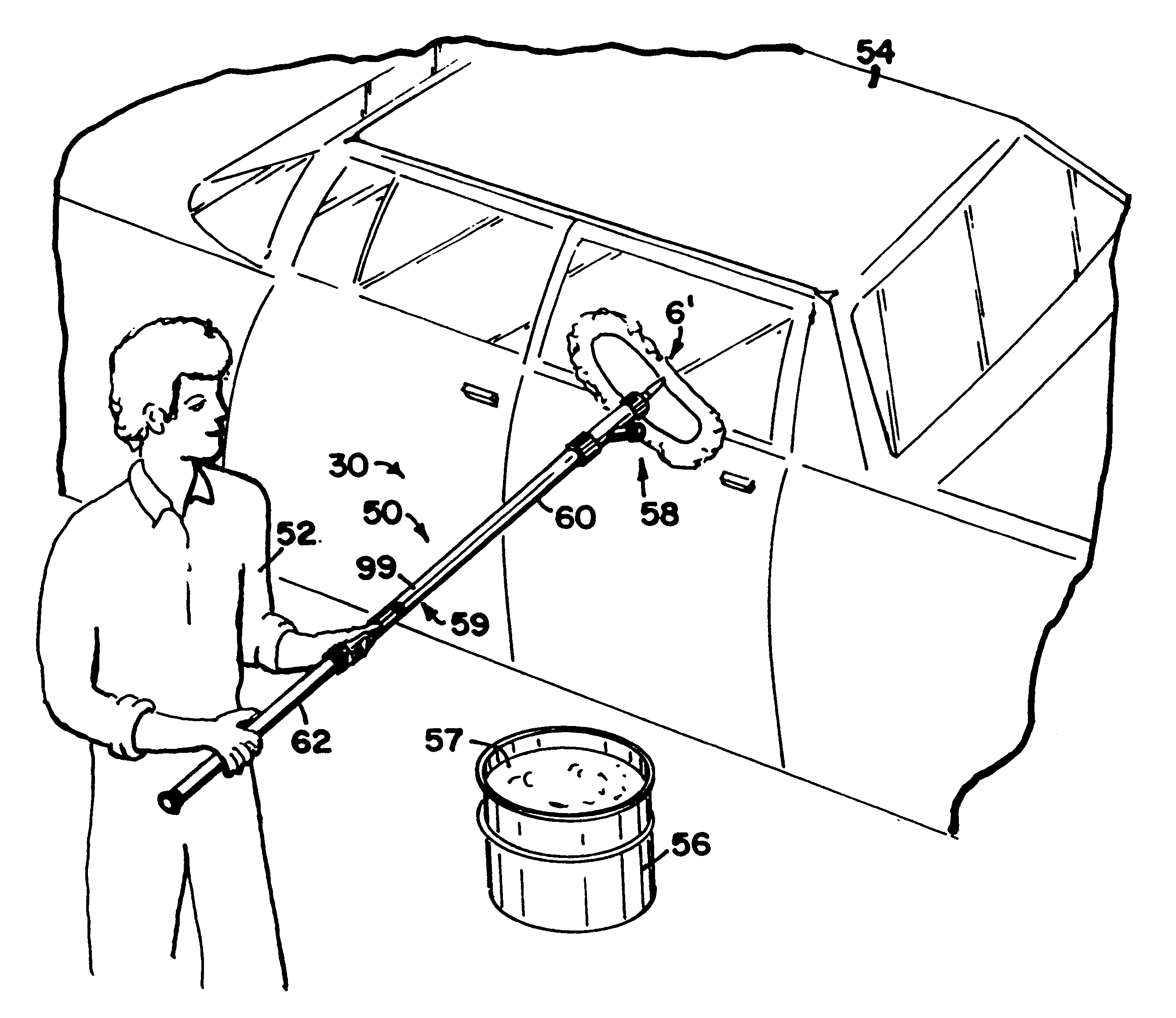
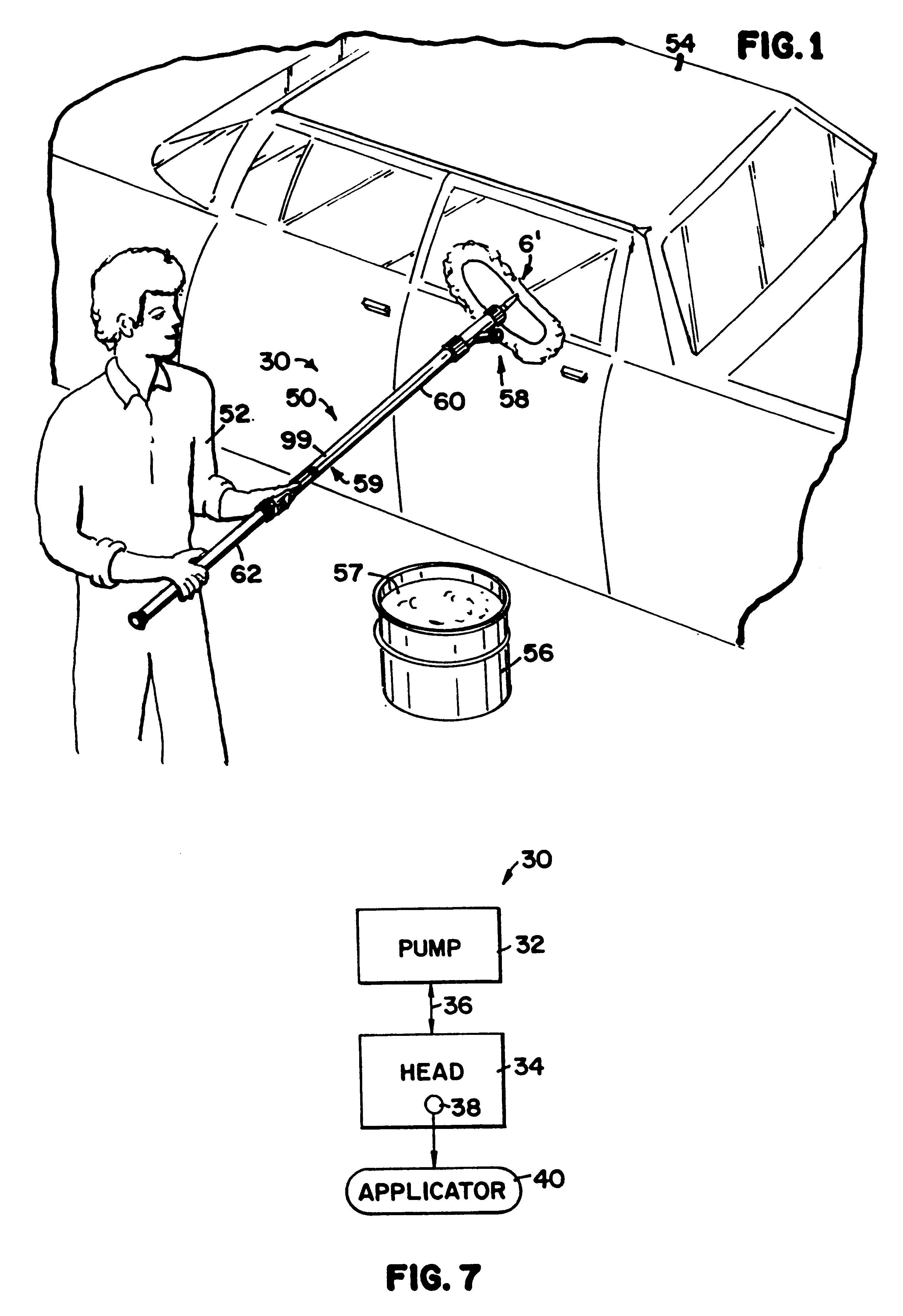
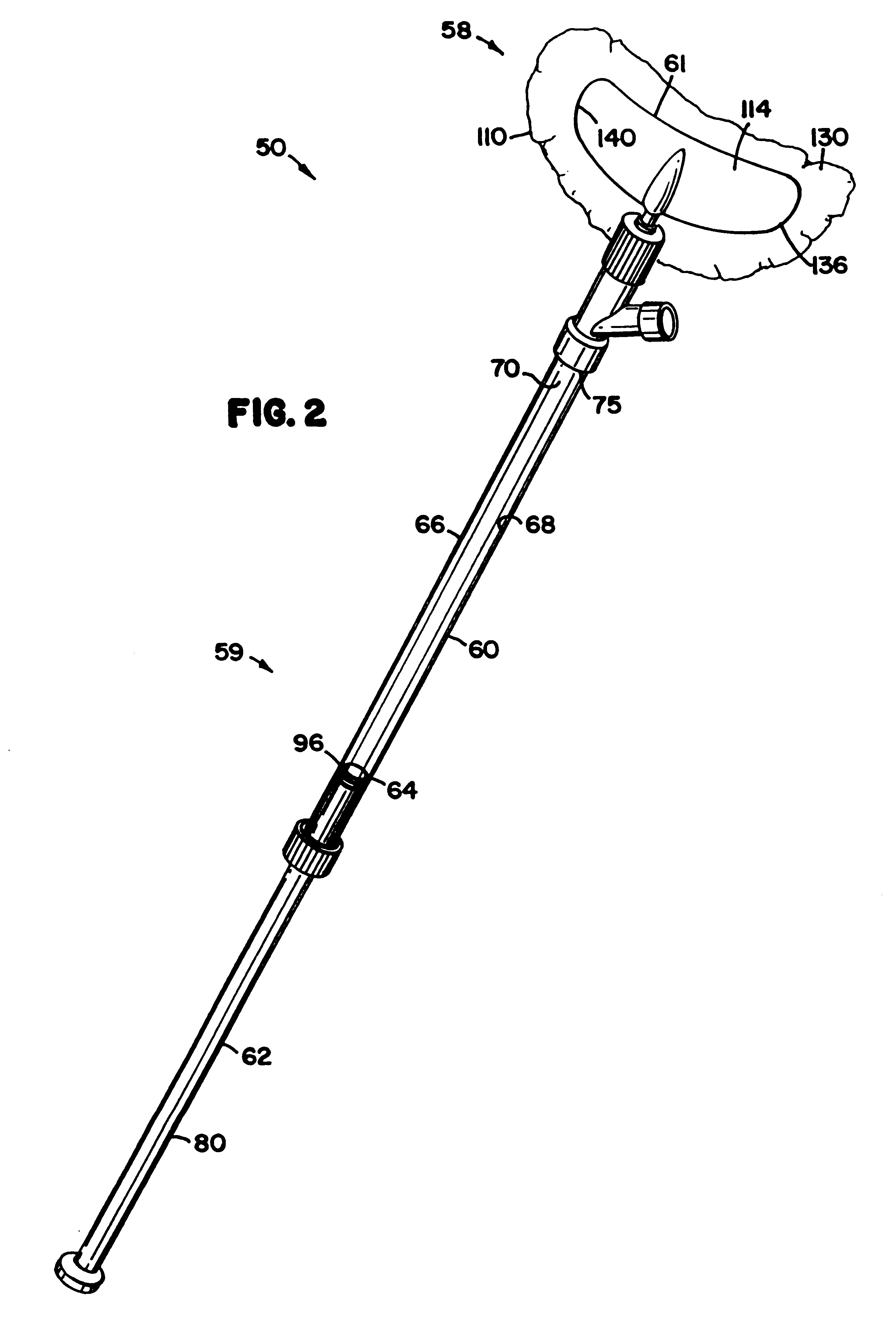
In operation, the user 52 will push the plunger 62 at least partially or fully to the end 75 of the tubular member 60. The user 52 will then submerge the discharge head 58 into liquid, such as cleaning solution 57. The user 52 will move the plunger 62 away from the end 75 to create a pressure differential between the liquid reservoir 70 and the source of liquid. As the plunger 62 is pulled away from the discharge head 58, the liquid is drawn through the porous mitt 130. The liquid then flows into the channel 122. From there, the liquid flows into the liquid reservoir 68. It flows from the channel 122 into the liquid reservoir 68 by passing through the channel 154 in the stem 124, and then through the open channel in the end cap construction 160.

The liquid, such as cleaning solution 57, is then dispensed through the mitt 130. This step may be done by sliding the plunger 62 into the reservoir 68 and toward the discharge head 58. This may also include pressing the mitt 130 against the ...


PUM

PropertyMeasurementUnit
surface areaaaaaaaaaaa
radiusaaaaaaaaaa
radiusaaaaaaaaaa

Abstract

A liquid dispenser arrangement includes a self-contained pump and a discharge head. The pump has a liquid reservoir, while the discharge head has an applicator construction and an aperture. The aperture will be in liquid flow communication with the liquid reservoir. The discharge head is constructed and arranged to selectively take in liquid from an external liquid source through the aperture and convey the liquid to the liquid reservoir, when a pressure differential is established between the liquid reservoir and the external liquid source by the pump. The discharge head is also constructed and arranged to selectively eject liquid from the liquid reservoir through the aperture for distribution by the applicator construction. The applicator construction preferably includes a molded, flexible member with the aperture being in a portion of the flexible member. Methods of assembly and use are also disclosed.

Description

This disclosure concerns liquid dispenser and distribution constructions. More specifically, this disclosure describes apparatus and methods for dispensing a cleaning solution to wash structures such as vehicles, windows, boats, or other objects.It is desirable to keep the exterior of objects, such as a vehicle, clean. Salt and other contaminants from the environment can cause a vehicle to rust. Various methods have been employed to wash the surfaces of objects. For example, a hose conveying water and a washcloth or brush have been used. Further, a brush attached to an elongated handle has been used. Other types of constructions and methods are also known.Improvements in apparatus and methods for washing objects such as vehicles or other structures are desirable.SUMMARY OF THE DISCLOSUREIn one aspect, the disclosure describes a liquid dispenser arrangement including a self-contained pump including a liquid reservoir and a discharge head having an applicator construction and an apert...

Claims


Application Information

Patent Timeline
Patent Type & Authority Patents(United States)
IPC IPC(8): A47L1/15A47L1/00A47L13/20A47L13/22B08B1/00B08B3/04B60S3/04F04B9/00F04B9/14A47L1/08A47L13/26B08B7/04B60S1/66
CPCA47L1/15A47L13/22B08B1/00B08B3/04B60S3/047F04B9/14A61P35/00
Inventor BRUGGEMAN, THOMAS W.BRUGGEMAN, DANIEL J.LEVER, CHARLES J.KOHS, STEPHEN C.
Owner WAGNER SPRAY TECH CORP
Why Eureka
Try Eureka