Gas discharge tube

Active Publication Date: 2005-10-20
HAMAMATSU PHOTONICS KK
View PDF23 Cites 120 Cited by
  • Summary
  • Abstract
  • Description
  • Claims
  • Application Information

AI Technical Summary

Benefits of technology

[0012] Moreover, it is preferable that the third opening comprises not only a straight section, for narrowing the discharge path, extending in the direction of the optical axis with an equal diameter, but also an spread section extending in the direction of the optical axis such that a diameter thereof increases from an end portion of the straight section on the side of the anode portion toward the second opening. The spread section has a function of improving the starting properties of the lamp and

Problems solved by technology

In the conventional gas discharge tube described above, however, there are problems as follows.
In the gas discharge tube, in case where light with high luminance is to be created, it is insufficient to simply provide plural stages of the discharge path li

Method used


Image

  • Gas discharge tube
  • Gas discharge tube
  • Gas discharge tube

Examples


first embodiment

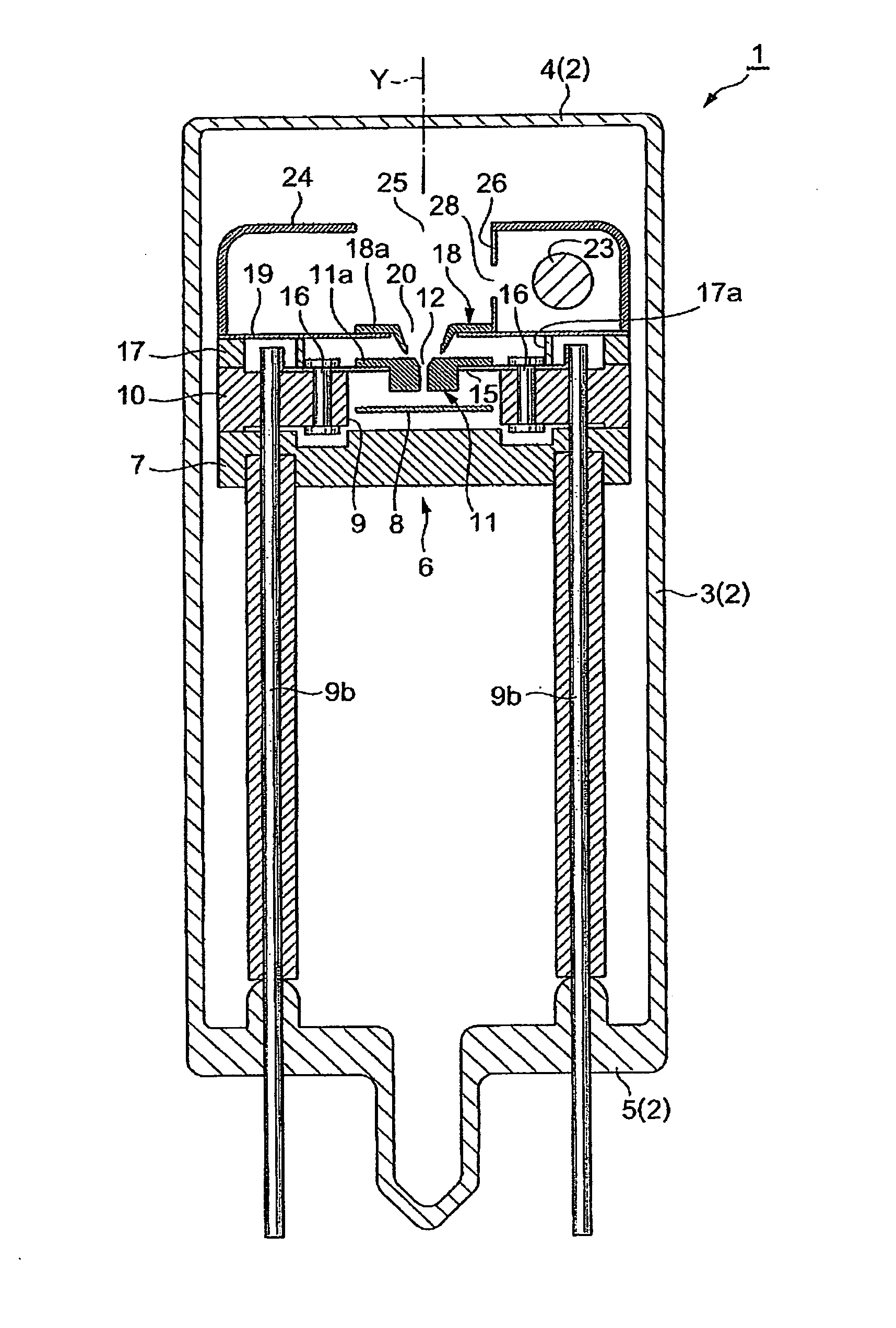
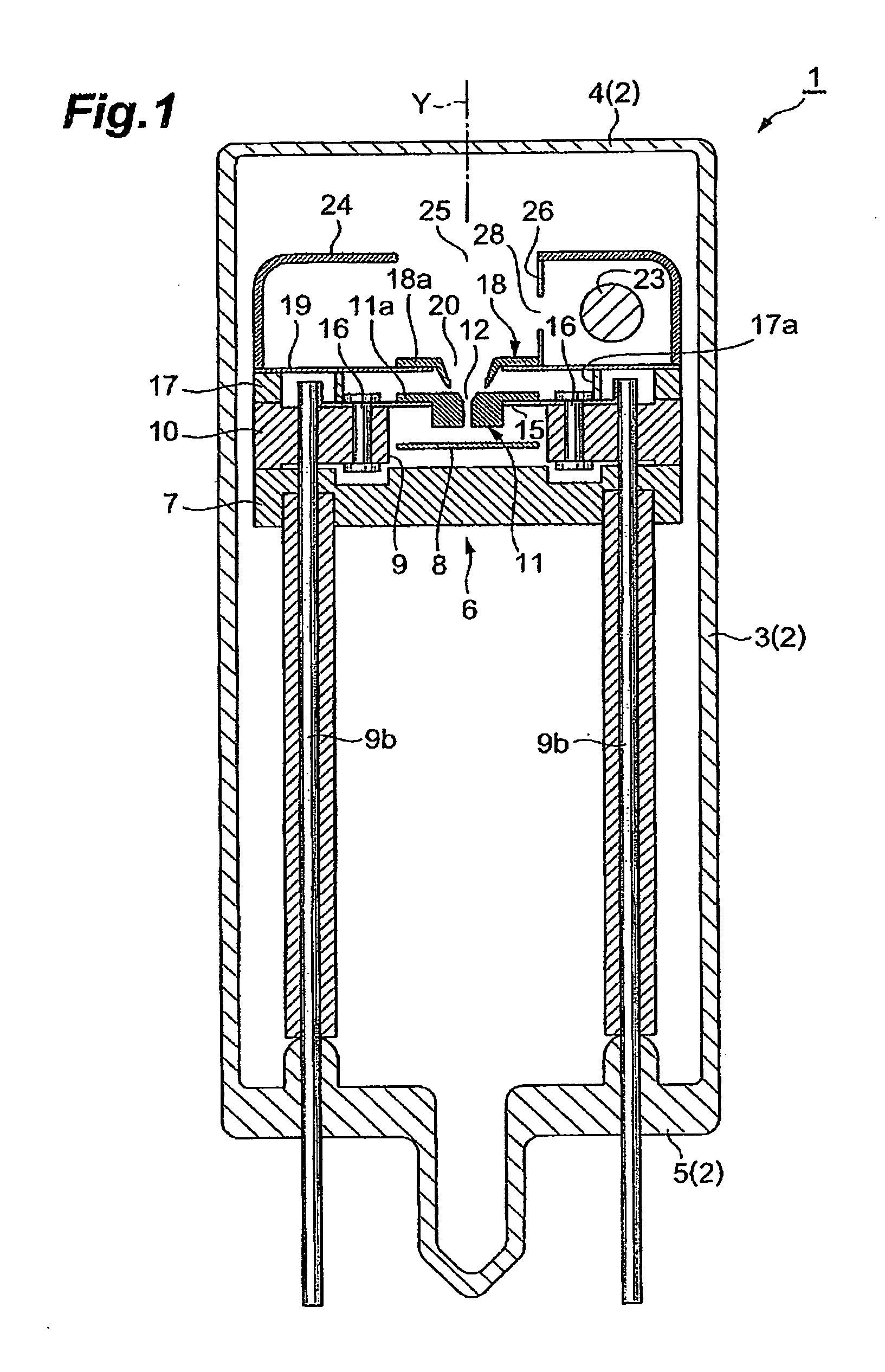
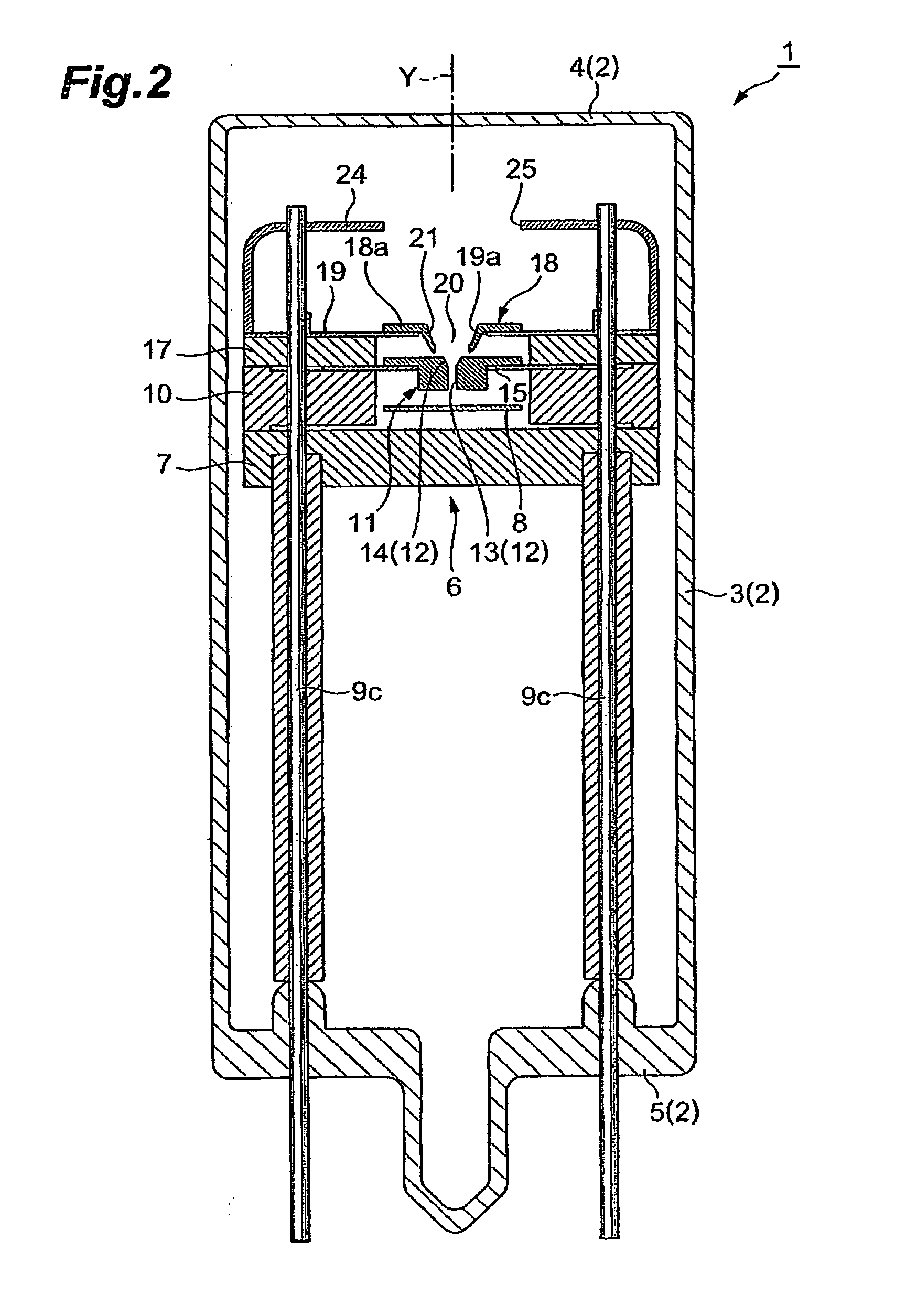
[0033] As shown in FIG. 1 and FIG. 2, a gas discharge tube 1 is a deuterium lamp of a head on type. The discharge tube 1 has a sealed envelope 2 made of glass in which deuterium gas has been enclosed in an amount of about several hundreds Pa, and the sealed envelope 2 comprises a light emitting window 4 which seals one side of a cylindrical side tube 3 and a stem 5 which seals the other side of the side tube 3. Then, a light emitting assembly 6 is accommodated in the sealed envelope 2.

[0034] This light emitting assembly 6 has a disc-like first supporting portion 7 formed of electrically insulating ceramics. Two lead portions (not shown) which extend from an anode plate (an anode portion) 8 extending in a direction perpendicular to an optical axis Y are caused to abut on the first supporting portion 7. Then, each lead portion is electrically connected to a distal end portion of a first stem pin (not shown) for an anode oriented upstanding on the stem 5 to extend in a direction of th...

second embodiment

[0047] Explanation herein is confined for substantially different matters from the first embodiment, and constituent portions equal or equivalent to those in the first embodiment are denoted with the same reference numerals and explanation thereof will be omitted.

[0048] As shown in FIG. 4 and FIG. 5, a gas discharge tube 27 is a deuterium lamp of a head on type. In the gas discharge tube 27, a third discharge path limit portion 29 made up of electrically conductive metal (for example, molybdenum, tungsten, or alloy made of these materials) is disposed in a midway of the discharge path between the second discharge path limit portion 11 and the anode plate 8, and a flange portion 29a of the third discharge path limit portion 29 is welded to an electrically conductive plate 28.

[0049] Further, a third opening 30 extending in the direction of the optical axis Y is provided at a central portion of the third discharge path limit portion 29, and the third opening 30 has a straight section...

third embodiment

[0057] As shown in FIG. 6 and FIG. 7, a gas discharge tube 35 is a deuterium lamp of a side on type. The discharge tube 35 has a sealed envelope 36 made of glass in which deuterium gas has been enclosed in an amount of about several hundreds Pa. The sealed envelope 36 comprises a cylindrical side tube 37 whose one end has been sealed, and a stem 38 for sealing the other end of the side tube 37, and on portion of the side tube 37 is utilized as a light emitting window 39. Then, a light emitting assembly 40 is accommodated in the sealed envelope 36.

[0058] The light emitting assembly 40 has a first supporting portion 41 made of electrically insulating ceramics and a second supporting portion 42 made of electrically insulating ceramics, and a recessed portion P is formed on a front face with cooperation of the first supporting portion 41 and the second supporting portion 42. Then, an anode plate 43 is accommodated inside the recessed portion P. A back face of the anode plate 43 is elec...


PUM


Abstract

In the gas discharge tube according to the present invention, there is carried out narrowing of the discharge path with cooperation of the first opening 20 and the second opening 12 in order to obtain higher luminance of light. Further, in order to maintain excellent starting-properties of a lamp even if the discharge path is narrowed, a predetermined voltage is applied to a second discharge path limit portion 11 externally. Thereby, a positive or active starting discharge is produced in such a manner as to pass through the first opening 20. Further, the second opening 12 is comprised of not only a straight section 13 extending in a direction of an optical axis Y, but also a spread section 14 extending from an end portion of the straight section 13 toward the first opening 20. The spread section 14 has a function of improving the starting properties of the lamp and forms an arc ball, and the straight section has a function of improving a plasma density. Thereby, discharge at a starting time is made easy to pass through the second discharge path limit portion 11. As a result, a rapid start of discharge between a cathode 23 and an anode portion 8 is achieved in the second discharge path limit portion 11, and that contributes to proper generation of an arc ball after lighting.

Description

TECHNICAL FIELD [0001] The present invention relates to a gas discharge tube used as a light source for a spectroscope, a chromatography, or the like. BACKGROUND ART [0002] There is disclosed as a prior art pertaining to the related technical field a gas (deuterium) discharge tube in Japanese Patent Laid-Open (Tokukai) No. H06-310101 publication. In a gas (deuterium) discharge tube described in this publication, there are arranged two metal partition walls within the discharge path between an anode and a cathode, wherein each of the metal partition walls is provided with small holes, whereby the discharge path is caused to be narrowed. As a result, it is made possible to obtain light with a high luminance by means of the small holes on the discharge path. Further, provision of three or more metal partition walls could lead to a further higher luminance. The smaller holes are made, the higher luminance of light there can be obtained. DISCLOSURE OF THE INVENTION [0003] In the conventi...

Claims


Application Information

Patent Timeline
IPC IPC(8): H01J61/10H01J61/54H01J61/68
CPCH01J61/54H01J61/10H01J61/68
Inventor ITO, YOSHINOBUMATSUSHITA, KOJIITO, MASAKI
Owner HAMAMATSU PHOTONICS KK
Why Eureka
Try Eureka