Construction Machine

a construction machine and construction technology, applied in the direction of servomotors, constructions, servometer circuits, etc., can solve the problems of pump load rise, pump pressure rise, and the minimum delivery rate of hydraulic pumps cannot be relieved to the tank, so as to enhance the engine starting property in a low temperature environment and low cost

Active Publication Date: 2021-08-26
NIHON KENKI CO LTD
View PDF0 Cites 1 Cited by
  • Summary
  • Abstract
  • Description
  • Claims
  • Application Information

AI Technical Summary

Benefits of technology

[0012]According to the construction machine according to the present invention, an engine starting property in a low temperature environment can be enhanced at low cost.

Problems solved by technology

This is because the viscous friction of the hydraulic working fluid is increased at a low-temperature time and, therefore, a rise in the pilot pressure is delayed.
Therefore, the minimum delivery rate of the hydraulic pump cannot be relieved to the tank, the pressure inside a line rises, and pump load is raised.
As a result, a problem that an engine starting property at a low-temperature time is lowered is generated such as engine load becoming excessively large or the engine stalling and stopping (engine stall)

Method used


Image

  • Construction Machine
  • Construction Machine
  • Construction Machine

Examples


embodiment 1

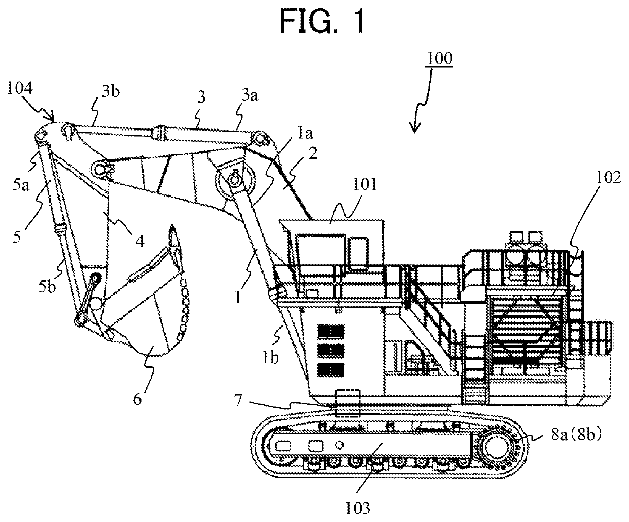
[0024]FIG. 1 is a side view depicting a hydraulic excavator according to a first embodiment of the present invention.

[0025]The hydraulic excavator 100 includes: a lower track structure 103 having crawler type track devices 8a and 8b on respective left and right sides; and an upper swing structure 102 as a machine main body swingably mounted on the lower track structure 103. The upper swing structure 102 is driven to swing relative to the lower track structure 103 by a swing motor 7 as a swing hydraulic motor.

[0026]To the front side of the upper swing structure 102, a front work implement 104 as a work device for performing, for example, excavation is mounted in a vertically rotatable manner. Here, the front side refers to the direction in which an operator riding in a cab 101 faces (the leftward direction in FIG. 1).

[0027]The front work implement 104 has a boom 2, an arm 4, and a bucket 6. A base end portion of the boom 2 is connected to the front side of the upper swing structure 1...

embodiment 2

[0060]A hydraulic excavator 100 according to a second embodiment of the present invention will be described, the description being centered on differences from the first embodiment.

[0061]In the first embodiment, the electric pump 24 is driven in the case where the pilot line pressurization control section 40c detects the key ON state and where the low temperature sensing section 40a of the controller 40 detects a low temperature. However, since the pressure inside the line 27 is maintained by the delivery pressure of the pilot pump 13 after the engine 9 is started, it is wasteful on an energy basis to continue the driving of the electric pump 24. In addition, if the electric power of the battery 26 is consumed completely, there is a fear that the motor 25 cannot be driven, and the engine 9 cannot be started, at the time of the next engine starting. It is an object of the present embodiment to secure a good engine starting property in a low temperature environment, while restraining ...

embodiment 3

[0066]A hydraulic excavator 100 according to a third embodiment of the present invention will be described, the description being centered on differences from the first or second embodiment.

[0067]In the first or second embodiment, while the key switch 35 is in the key ON state in a low temperature environment, the electric pump 24 continues being driven by the motor 25. Therefore, if a long time has elapsed with the key switch 35 in the key ON state in the low temperature environment, lowering in the voltage of the battery 26 or heat generation in the motor 25 or the like may occur, resulting in lowering the driving force of the motor 25. As a result, the delivery pressure of the electric pump 24 (the pressure inside the line 27) is lowered, and the unloading valve 21 would be closed. Even if the operator thereafter operates the key switch 35 to the engine ON state, the minimum delivery rate of the one-side tilting pump 12 cannot be relieved to the tank 20. Therefore, the pump load ...


PUM


Abstract

It is an object of the present invention to provide a construction machine having a good engine starting property in a low temperature environment.
The construction machine of the present invention includes: an electric pump having a delivery port connected to a line part of a pilot line, the line part connecting a pilot pump with a pilot control valve; a motor that drives the electric pump; and a temperature sensor that measures a temperature of a hydraulic working fluid delivered from the pilot pump. A controller starts driving of the motor in the case where a key switch is operated from a key OFF state to a key ON state and where the temperature of the hydraulic working fluid measured by the temperature sensor is lower than a predetermined temperature.

Description

TECHNICAL FIELD[0001]The present invention relates to a construction machine such as a hydraulic excavator on which is mounted a hydraulic drive system for driving a hydraulic actuator.BACKGROUND ART[0002]In recent years, in the construction machines such as hydraulic excavators and wheel loaders, energy saving of a hydraulic system has come to be an important item of development. In general, energy consumption of a hydraulic pump is desired to be suppressed at non-operating stand-by times. However, since a variable displacement swash plate type piston pump (hereinafter referred to as a one-side tilting pump) used for the hydraulic pump has a minimum delivery rate (hereinafter referred to as a minimum delivery rate), and delivers a hydraulic working fluid even when a delivery control command value is zero, the hydraulic pump consumes energy at stand-by time. Therefore, an unloading valve for relieving the minimum delivery rate to the tank at stand-by time of the excavator is provide...

Claims


Application Information

Patent Timeline
Patent Type & Authority Applications(United States)
IPC IPC(8): E02F9/22F15B11/08
CPCE02F9/2235F15B11/08E02F9/2267E02F9/2296F15B2211/851F15B2211/50536F15B2211/45F15B2211/526F15B2211/528F15B2211/66F15B2211/6343F15B2211/6355F15B2211/20576F15B2211/20523F15B2211/20515F15B21/045E02F9/2289E02F9/2242E02F9/2228E02F9/2285E02F9/2217E02F9/2246
Inventor SAITOH, TEPPEIHIRAKU, KENJIAIHARA, MITSUO
Owner NIHON KENKI CO LTD
Why Eureka
Try Eureka