Ionizing sputtering method

a technology of ionizing sputtering and sputtering chamber, which is applied in the direction of vacuum evaporation coating, coating, electric discharge tube, etc., can solve the problems of difficult formation of a film with a high bottom coverage, critical flaws in the device characteristics, and thin barrier film at the bottom of the hole, so as to achieve less generation of particulates, reduce the formation of particulates, and greatly improve the bottom coverage

Inactive Publication Date: 2002-09-03
ANELVA CORP
View PDF10 Cites 29 Cited by
  • Summary
  • Abstract
  • Description
  • Claims
  • Application Information

AI Technical Summary

Benefits of technology

As can be inferred from FIGS. 3 and 4, the bottom coverage is greatly improved over that obtained with a conventional device such as a low-pressure, long-distance sputter device, even when no shield 6 is inst

Problems solved by technology

For holes with a high aspect ratio, it is difficult to form a film with a high bottom coverage, i.e., the ratio of the deposition rate on the hole bottom to the deposition rate on the peripheral surfaces of the hole.
A decrease in the bottom coverage can lead to a thinner barrier film at the bottom of the hole and to critical flaws in the device characteristics, such as junction leakage.
A problem with collimation sputtering is that sputter particles accumulate on the collimator portion, and the resulting loss of material decreases the deposition rate.
A problem with low-pressure,

Method used


Image

  • Ionizing sputtering method
  • Ionizing sputtering method
  • Ionizing sputtering method

Examples


example 2

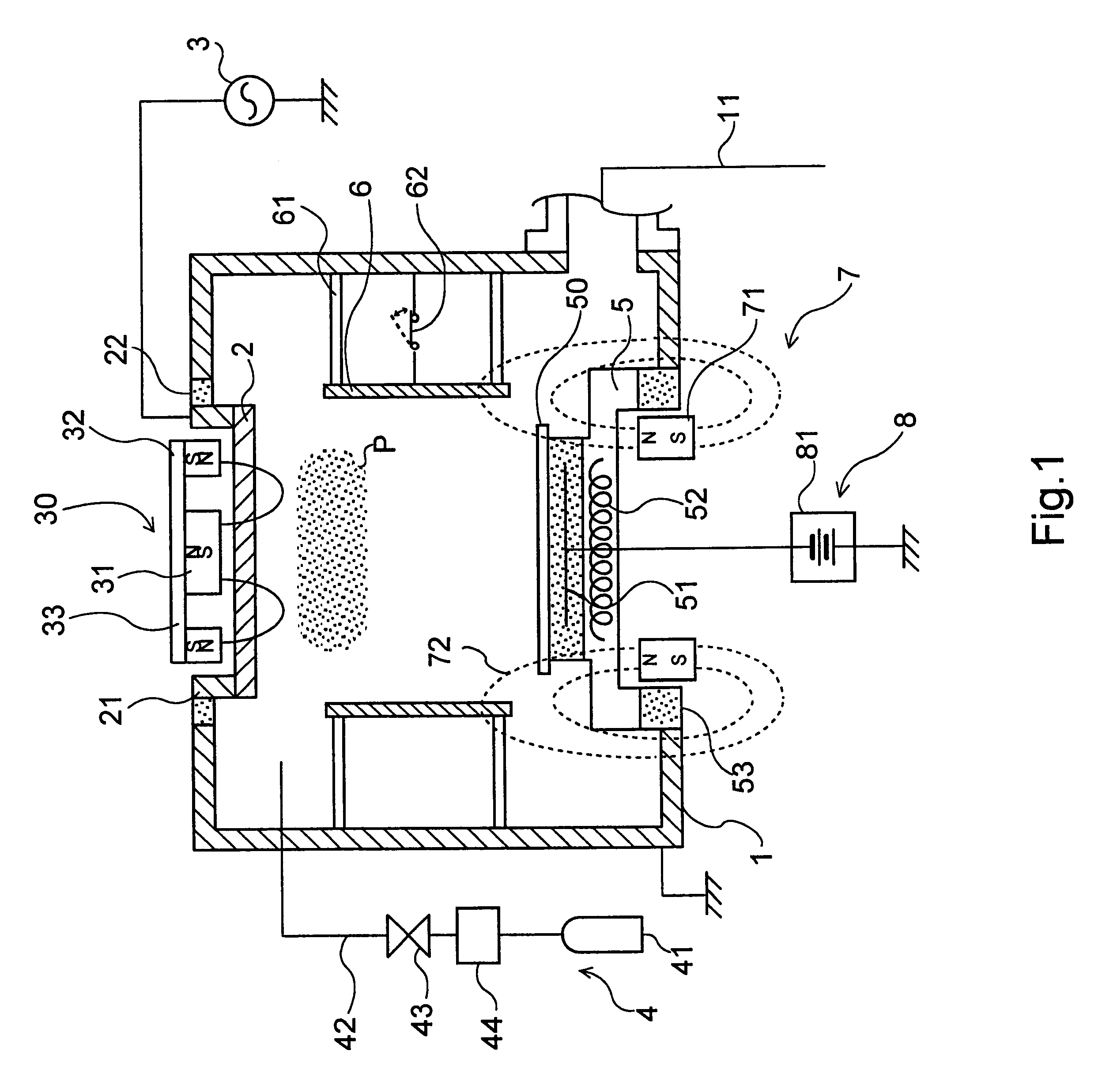
Sputtering can be carried out under the following conditions as a practical example (hereinafter referred to as the second practical example) of producing a titanium nitride thin film for use as a barrier film.

Sputtering power source 3: 13.56 MHz, 8 kW output

Material of target 2: titanium

Type of process gas: mixed gas of argon and nitrogen

Flux of process gas: argon 25 cc / min; nitrogen 75 cc / min

Pressure during film deposition: 45 mTorr

Substrate-biasing voltage: -600 V

Temperature of substrate holder 5 during film deposition:

200.degree. C.

Deposition rate: 200 angstroms / min

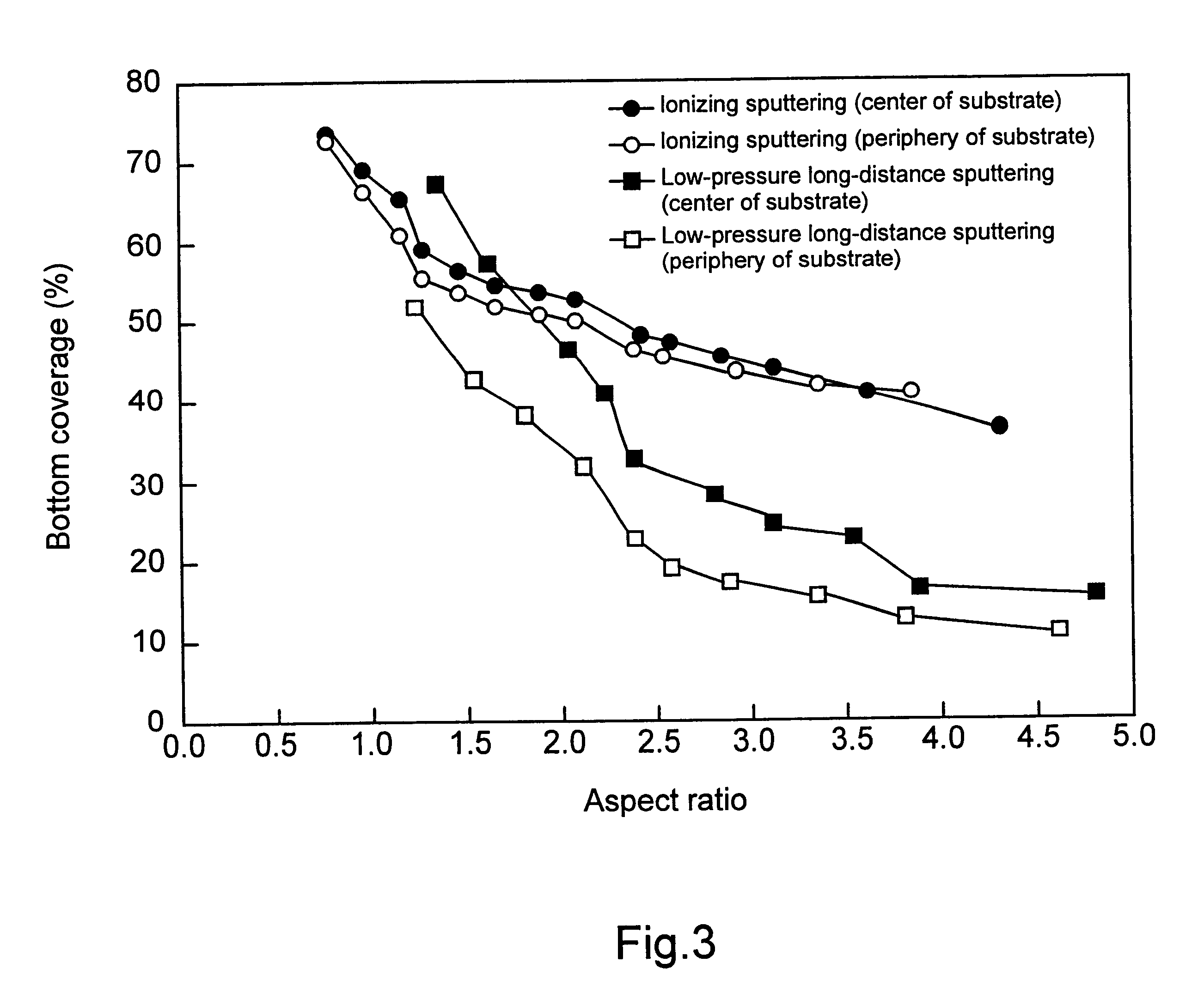
FIG. 3 is a graph of the results obtained by depositing a film under the conditions of the abovementioned first practical example. The graph shows the relationship of bottom coverage to the aspect ratio of the hole. For the sake of comparison, data are also shown for a conventional, low-pressure, long-distance sputter device. The data for this low-pressure, long-distance sputtering were obtained under conditions compr...


PUM

PropertyMeasurementUnit
Pressureaaaaaaaaaa
Pressureaaaaaaaaaa
Frequencyaaaaaaaaaa

Abstract

To form a film by ionized sputtering with good bottom coverage for holes with a high aspect ratio, and to simplify the structure inside and out of the sputter chamber, a target 2 is provided inside a sputter chamber 1 equipped with an exhaust system 11 and is sputtered by a sputtering power source 3. The released sputter particles are made to arrive at a substrate 50 to form a film. The sputtering power source 3 sends electric power of at least 5 W/cm2 to a target 2, and the sputter particles are ionized in a plasma formed by this electric power alone. A cylindrical shield 6 may be provided between the target 2 and the substrate holder 5 to restrict the plasma formation space, and an electric field establishment means 8 may set up an electric field for extracting the ionized sputter particles from the plasma P and directing them at the substrate 50.

Description

This application claims priority under 35 U.S.C. .sctn..sctn. 119 and / or 365 to Japanese Application No. 9-155981 filed in Japan on May 28, 1997; the entire content of which is hereby incorporated by reference.1. Field of Industrial UtilizationThe present invention relates to a sputtering method used in the fabrication of various types of semiconductor devices. More particularly, it relates to an ionizing sputtering method utilized in the formation of films by the ionization of sputter particles.2. Description of Related ArtWith semiconductor devices, such as various types of memory and logic devices, a sputtering process is used in the formation of various wiring films, and in the production of barrier films that prevent the interdiffusion of different layers, and sputter devices are commonly used for this purpose. There has recently been a great need for such sputtering devices to allow the inner surfaces of holes formed in a substrate to be coated with a good degree of coverage.A...

Claims


Application Information

Patent Timeline
IPC IPC(8): C23C14/04C23C14/35H01J37/32H01J37/34C23C14/34H01L21/768H01L21/70C23C14/46
CPCC23C14/046C23C14/345C23C14/351H01J37/3408H01L21/76877C23C14/34
Inventor SASAKI, MASAOFUNATO, KIYOHIKO
Owner ANELVA CORP
Why Eureka
Try Eureka