Diagnostic ultrasound transducer

a transducer and ultrasound technology, applied in the field of ultrasonic transducers, can solve the problems of cumbersome operation of the operator over the body of the patient, prone to breakage of flexible cables, and bulky and stiff transducer cables

Active Publication Date: 2009-02-05
SHENZHEN MINDRAY SCIENTIFIC CO LTD
View PDF21 Cites 85 Cited by
  • Summary
  • Abstract
  • Description
  • Claims
  • Application Information

AI Technical Summary

Benefits of technology

[0028]If “T” electrodes are to be made, then the PCB may be embedded in the backing block during the forming of the backing block. The rigidity of the PCB (as compared with, for example, a flex circuit), makes it much easier to ensure that the PCB location is fixed in the backing blocker (the structure that acts as a frame and mold for manufacturing the backing block), with less or no need for restraining or other supporting structures that also get embedded in the backing block and may cause image noise.

Problems solved by technology

This reality leads to several challenges and trade-offs relating to such issues as, among many others, cross-talk, impedance, physical robustness, heat, integrity and ease of bonding, manufacturing cost and complexity, and even comfort in use.
For example, strong lead wires may provide physical robustness, but they may also cause the transducer cable to be so bulky and stiff that it is cumbersome for an operator to maneuver over the body of a patient.
However, fine wires or traces that allow for a light, flexible cable are more prone to breaking.
As another example, certain transducer structures may be specially designed to be manufactured with certain materials, such as in a backing layer, but may then be difficult to adapt to new materials without difficult and costly changes in the structure and manufacturing procedures.

Method used


Image

  • Diagnostic ultrasound transducer
  • Diagnostic ultrasound transducer
  • Diagnostic ultrasound transducer

Examples


Embodiment Construction

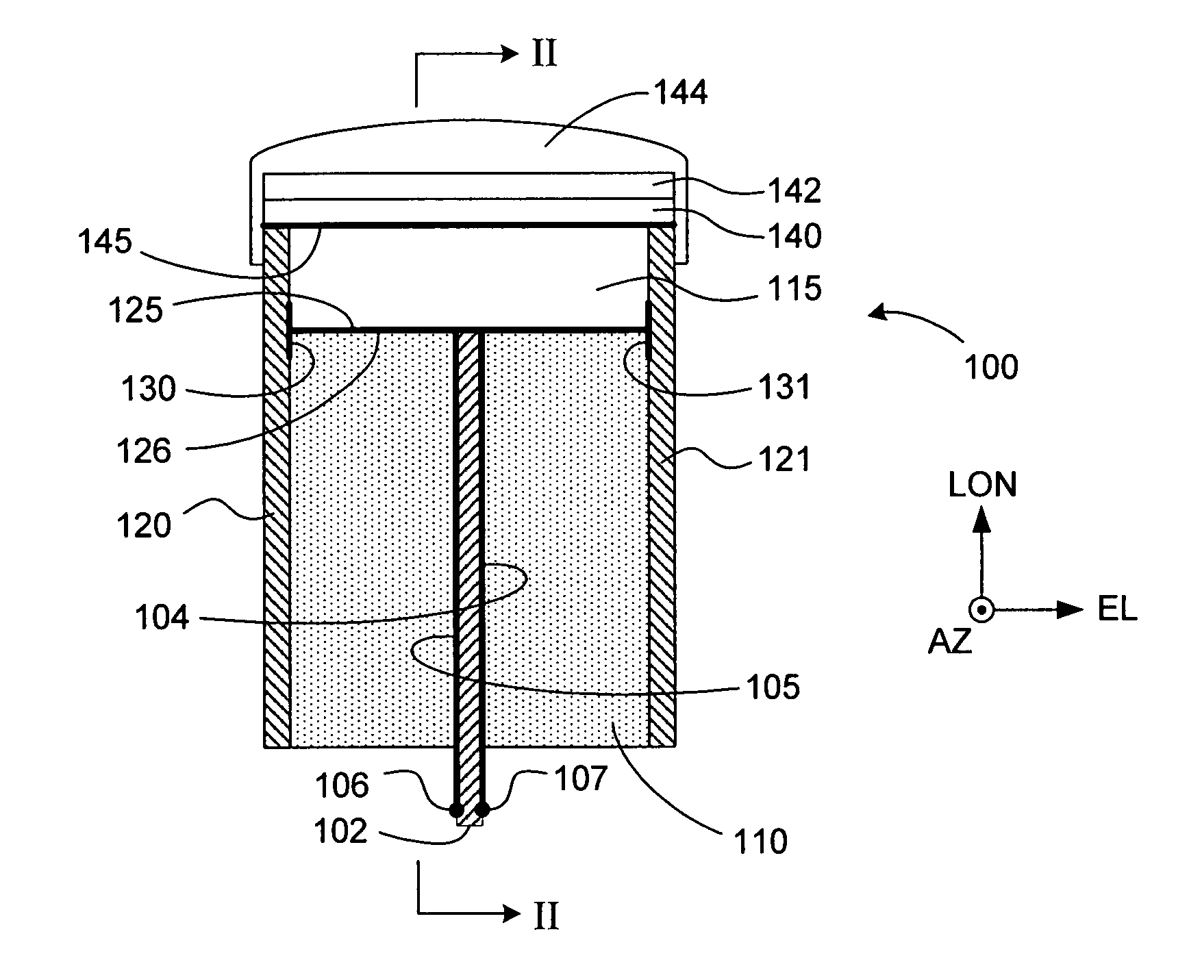
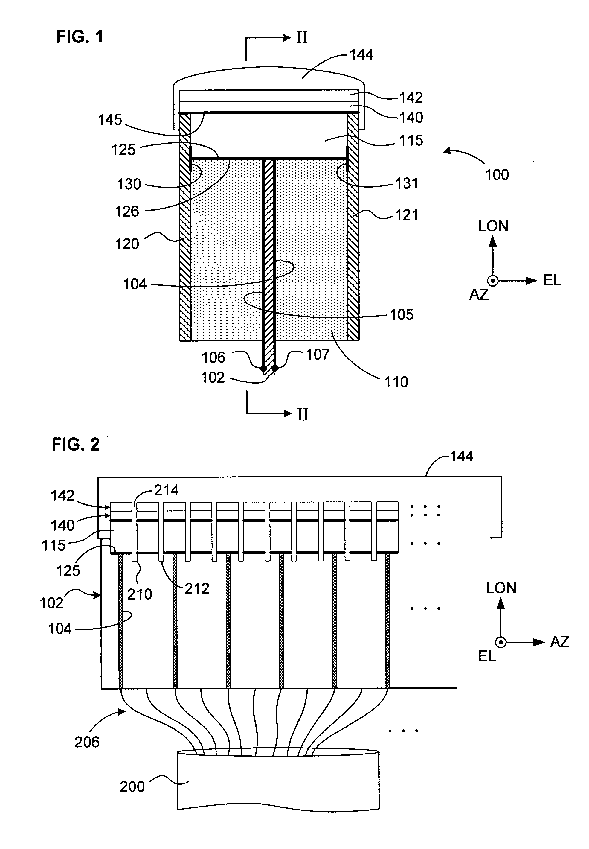
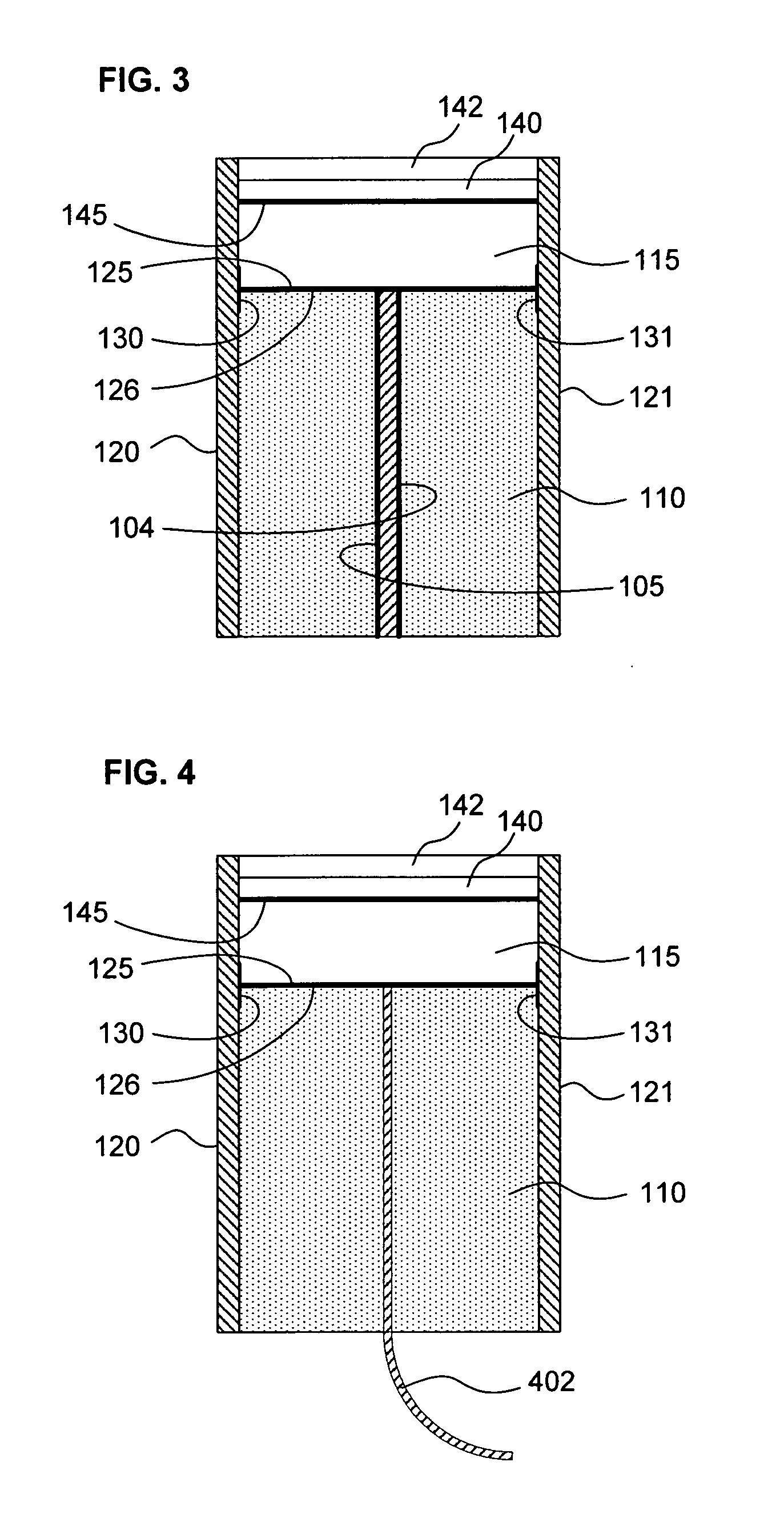
[0035]FIG. 1 shows a partially cut-away view from the side of the internal structure of an ultrasound probe, that is, transducer 100 according to one embodiment of the invention. In FIGS. 1 and 2, coordinate systems indicating the conventional reference directions are indicated. Here, AZ, EL, and LON indicate the azimuthal, elevational, and longitudinal directions. The longitudinal direction, which is sometimes referred to as the axial direction, is the direction in which it is assumed that ultrasound energy will primarily radiate from each element of the transducer array. Viewed as in FIG. 1 and as the transducer is used in practice, the top of the transducer is the distal end and the bottom is the proximal end.

[0036]In particular, FIG. 1 shows one of typically many elements in an ultrasound transducer array—oriented as in FIG. 1, the array elements extend perpendicular to the plane of the figure, that is, in an azimuthal direction. Each element of the array will, in typical implem...


PUM

PropertyMeasurementUnit
thickaaaaaaaaaa
areaaaaaaaaaaa
electrically conductiveaaaaaaaaaa

Abstract

An ultrasound transducer includes an array of PZT elements mounted on a non-recessed distal surface of a backing block. Between each element and the backing block is a conductive region formed as a portion of a metallic layer sputtered onto the distal surface. Traces on a longitudinally extending circuit board—preferably, a substantially rigid printed circuit board, which may be embedded within the block—connect the conductive region, and thus the PZT element, with any conventional external ultrasound imaging system. A substantially “T” or “inverted-L” shaped electrode is thereby formed for each element, with no need for soldering. At least one longitudinally extending metallic member mounted on a respective lateral surface of the backing block forms a heat sink and a common electrical ground. A thermally and electrically conductive layer, such as of foil, transfers heat from at least one matching layer mounted on the elements to the metallic member.

Description

FIELD OF THE INVENTION[0001]This invention relates to an ultrasonic transducer for use in diagnostic imaging.BACKGROUND OF THE INVENTIONDescription of the Related Art[0002]The importance of diagnostic ultrasound imaging is widely recognized, and has grown as imaging resolution and the range of available uses and features have steadily increased. Once an expensive luxury available only in the best-equipped hospitals, diagnostic ultrasound imaging is now a commonly and almost routinely offered procedure even in some individual physician's offices. Perhaps more importantly, some ultrasound imaging systems are now portable and inexpensive enough to have even in small offices, or in places such as in developing countries with relatively small budgets for such diagnostic tools.[0003]The quality of an ultrasound image is directly affected by many factors and in particular by the properties of the transducer used to generate the necessary pattern of ultrasonic signals and to receive their e...

Claims


Application Information

Patent Timeline
Patent Type & Authority Applications(United States)
IPC IPC(8): H04R17/00B06B1/06H01L41/08H01L41/22
CPCB06B1/0622Y10T29/49005H04R31/00H04R2201/029H04R31/006H01L41/47H01L41/293H04R2430/00G10K11/18B06B3/00B06B1/0292H04R2203/00H01L41/273Y10T29/49002Y10T29/4908Y10T29/49172Y10T29/49194Y10T29/49007Y10T29/49798Y10T29/42G10K11/002A61B8/4483H10N30/053H10N30/063H10N35/01
Inventor GUO, XIAOCONG
Owner SHENZHEN MINDRAY SCIENTIFIC CO LTD
Why Eureka
Try Eureka