
Plasma whirl reactor apparatus and methods of use

a whirl reactor and plasma technology, applied in plasma welding apparatus, machine/engine, manufacturing tools, etc., can solve the problems of shale gas developers in dire need of water recycling technologies, the potency drawdown of the two major drinking water sources, and the inability to blend well with salt water, etc., to achieve the anisotropy of the sputter etch, reduce the chamber pressure, and high plasma density

Active Publication Date: 2016-09-13
FORET PLASMA LABS
View PDF111 Cites 30 Cited by
  • Summary
  • Abstract
  • Description
  • Claims
  • Application Information

AI Technical Summary

Benefits of technology

The patent describes a method for igniting a plasma in a plasma reactor using a coil antenna and an RF power source. The technical effect of this method is that it allows for a more uniform high-density plasma, which is important for efficient plasma processing. The method also solves the problem of unreliable plasma ignition in typical inductively coupled plasma reactors by providing a means for inducing a plasma without the need for a separate auxiliary RF power source or the need to increase chamber pressure after ignition. Additionally, the method reduces the risk of wafer damage by avoiding a large spike in the D.C. bias on the wafer during plasma ignition.

Problems solved by technology

An emerging problem in the shale gas plays is “What to do with the Frac Flowback?” from shale gas wells.
First, many residents or opposing the use of drinking water purchased by operators from municipal drinking water treatment plants.
In addition, many regulators, officials and citizens are opposing the potential drawdown of the two major drinking water sources, ground water and surface water, due to a combination of recent draughts and the large volumes of water necessary for fraccing a well.
A second problem arises after the well has been fracced with water.
First, they strongly believe that the chemical Frac Package will not blend well with salt water.
The first major concern with operators is the liability of using this water that may contain both biological and chemical contaminants.
Hence, Shale Gas developers are in dire need of technologies for recycling water, in particular frac flowback.
Although there are many water treatment technologies capable of removing the aforementioned contaminants, the major contaminants posing a treatment problem and preventing operators and service companies from recycling frac flowback are water based polymers such as guar and xanthane gum.
Although the use of ozone produced in traditional manners, such as corona discharge, coupled with UV lamps or ultrasound to form an advanced oxidation system is a slight step-change it is not a game changing water treatment technology necessary to provide the impetus for operators to develop shale gas.
In addition, employing corona discharge ozone generators requiring dry air or dry oxygen is another added expense.
In particular, in the petroleum industry, the ever-increasing volume of associated water produced from the hydrocarbon reservoirs as a side product has become a major issue to be addressed by the producers.
Environmental awareness and regulations are increasingly challenging the producers to achieve a high degree of purification in the treated water streams prior to discharge or re-injection.
Simultaneously, the economical penalty for additional water treatment capacity and footprint of apparatus are major factors in budgeting and decision making for the producers.
One of the major problems with using activated carbon offshore for deepwater production platforms is that once the carbon is spent, it must be transported to shore then to a facility for reactivating the spent carbon.
Likewise, gas shale frac flowback requires removal of organics but activated carbon has not been a preferred solution because of the transportation logistics involved in reactivating or disposal of the spent carbon.
Ignition of a plasma is unreliable in a typical inductively coupled plasma reactor because it is difficult to couple to the plasma an ignition voltage high enough to excite the plasma.
Specifically, very low chamber pressures, typically about 0.5 milliTorr, are necessary to achieve high plasma density in the region adjacent the semiconductor substrate and to maximize anisotropy of the sputter etch, but the voltage necessary to ignite the plasma undesirably increases with decreasing chamber pressure.
Unfortunately, in an inductively coupled plasma reactor the very low chamber pressure and the lack of capacitive coupling make it very difficult to ignite a plasma in the chamber.
At the low pressure (i.e., 0.5 milliTorr) required for argon sputter etching, the required breakdown voltage may be close to or even exceed the capacity of the RF power source of the induction coil, making plasma ignition unreliable.
As a result, it may be necessary to make several attempts to ignite a plasma, greatly reducing the productivity of the plasma reactor.
A conventional technique for meeting the power requirement for plasma ignition is to connect an auxiliary RF power source to the induction coil during plasma ignition, but this requires additional hardware and expense.
However, pumping down the chamber pressure after plasma ignition (e.g., from 10 milliTorr during ignition to 0.5 milliTorr after ignition) requires a significant amount of time, during which the etch process will be carried out at a higher than ideal pressure, thereby causing poor etch profiles.
Also, the necessary time to pump down will adversely affect throughput of the etch reactor.
However, this tends to create a large spike in the D.C. bias on the wafer during plasma ignition, increasing the risk of wafer damage.
A disadvantage of this technique is that it either unduly increases capacitive coupling to the plasma if used to increase the plasma potential, thereby reducing the control over ion energy, or else, if grounded, it cuts off whatever capacitive coupling from the induction coil may exist, thereby making plasma ignition less reliable or more difficult.
He does not disclose nor is it obvious to leave the carbon rod within the torch and continuously feeding the carbon rod as a source of fuel.
Nor does the patent disclose a second carbon electrode.
Some of the compounds are highly refractory in nature and are difficult to decompose.
One frequently encountered problem with standard inductively coupled RF plasma systems is the difficulty of igniting and sustaining the plasma.
Plasma ignition is unreliable because coupling an ignition voltage high enough to generate the energetic species needed to produce the plasma is difficult.
Consequently, igniting plasmas at very low pressures and at high pressures is difficult.
Unfortunately for standard inductively coupled plasma technology, the absence of strong electric fields and the absence of strong capacitive coupling make it difficult to overcome the plasma ignition problems resulting from gas pressure and gas electronegativity.
At pressures that are too high or too low or for gases with high electronegativities, the required breakdown voltage may equal or exceed the capacity of the RF power source, making plasma ignition unreliable.
As a result, it may be necessary to make several attempts to ignite the plasma, greatly reducing the productivity and efficiency of the plasma process.
The unreliable plasma ignition can waste valuable process gases, can increase pollution problems, and can ruin valuable product
In addition to the problem of igniting the plasma, there is also the problem of poor plasma stability.
For instance, the plasma can go out while performing a process and cause the same unfortunate results that occur for unreliable plasma ignition.
Unfortunately, typical methods and apparatus for old-style inductively coupled RF plasma systems have characteristics that are undesirable for some applications.
In these projects, a large body of scientific information and knowledge has been accumulated, but product development and technology gaps exist.
In particular, oxy-combustion characteristics in a tangentially fired (T-fired) boiler are not well understood.
In fact, the cost of currently designed upgraders has put many projects on hold due to low crude oil prices.
However, there have been five major drawbacks and / or concerns in using plasma for industrial applications such as gasifying, cracking or steam reforming coal, petcoke, heavy oil, oil sand, oil shale, cracking methane and / or converting biomass to biochar.
The drawbacks are electrode life, heat rejection, plasma ignition, sustaining a plasma and plasma confinement.
Without a doubt the number one problem that must be solved in using plasma for the aforementioned applications is confinement due to the extreme temperatures the plasma facing material or refractory must survive in order to bridge the gap between R&D and commercialization.
Shutting down a reactor every other month for a turn around in order to reline the reactor or repair the refractory is not an option in many applications.
This is due primarily to heat loss due to cooling the electrodes.
This has been a major issue with using inductively coupled plasma (ICP) torches.
Likewise, the DOE and Universities are in dire need of a simple plasma reactor design for conducting plasma R&D such as confinement, rotation and testing plasma facing material.

Method used


Image

  • Plasma whirl reactor apparatus and methods of use
  • Plasma whirl reactor apparatus and methods of use
  • Plasma whirl reactor apparatus and methods of use

Examples


example 1

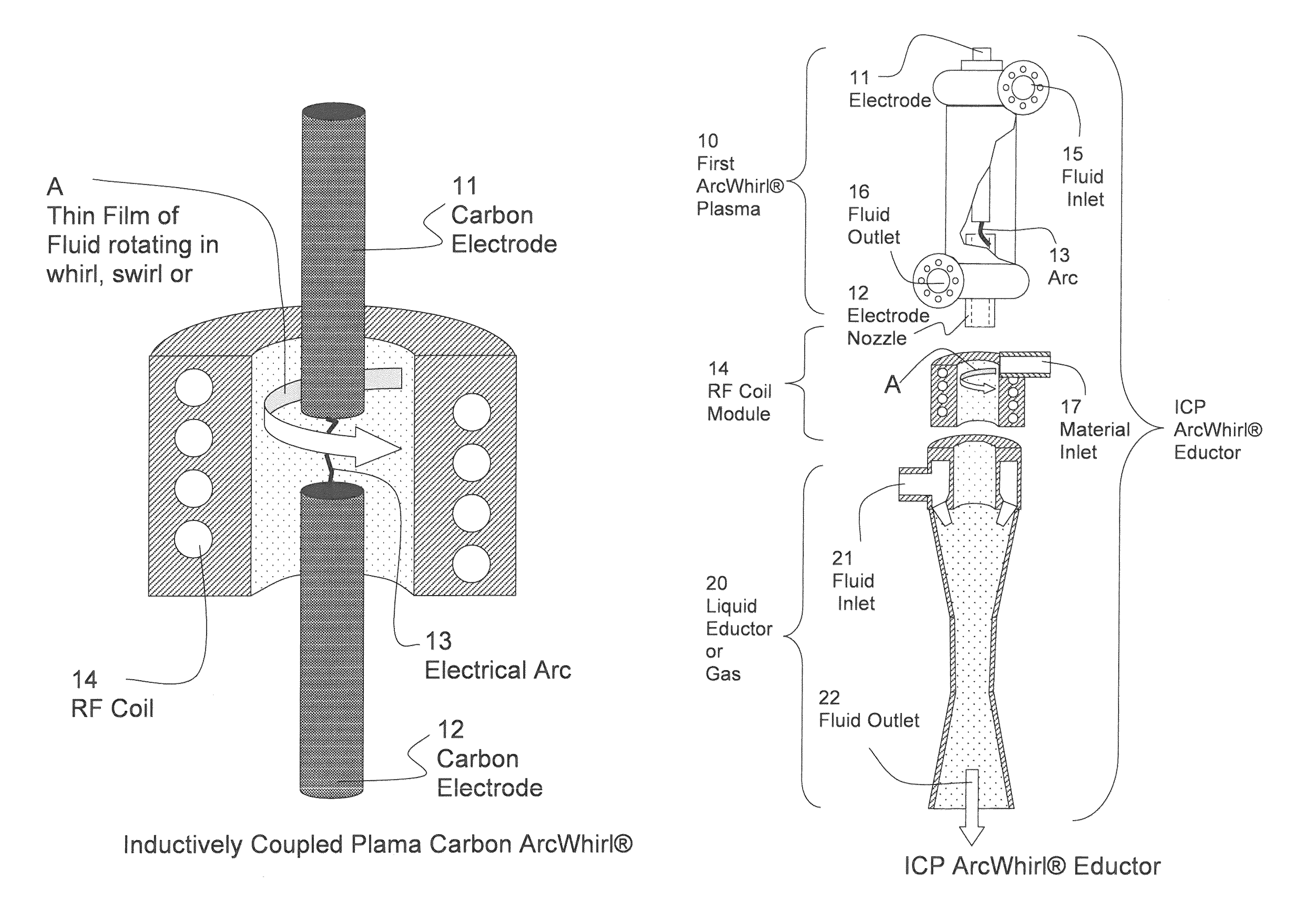
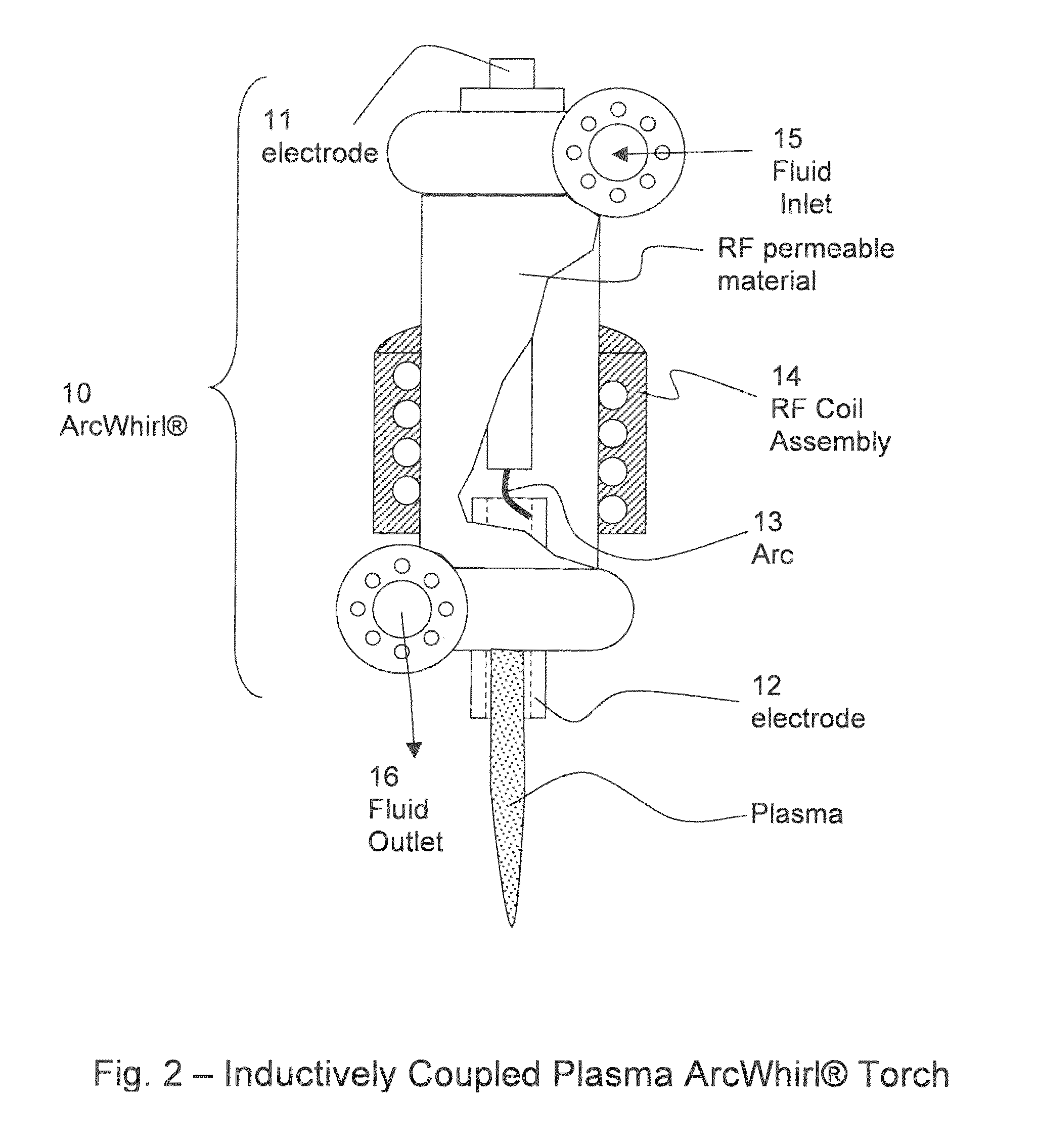
[0105]Returning to FIG. 2, fluid is flowed into the ArcWhirl Torch via inlet 15 and exits via outlet 16. A vortex will be formed with the center of the vortex operating at a slight vacuum. Since the ICP torch is open to the atmosphere then air will be drawn into the torch through the hollow electrode 12. It will be understood that a gas, such as air, oxygen, methane, diesel emissions and carbon dioxide for example can be introduced into the ICP ArcWhirl® torch in combination with the fluid via inlet 15.

[0106]The ICP ArcWhirl® Torch is ignited by first moving electrode 11 to touch the carbon vortex finder electrode 12. It is understood that one of the electrodes either 11 or 12 will be the cathode and the other will be the anode and accordingly electrically connected to a DC power supply. The DC power supply (not shown) is then turned on and a dead short is formed between electrodes 11 and 12. Next, electrode 11 is moved away from electrode 12 by means known in the art such as a line...

example 2

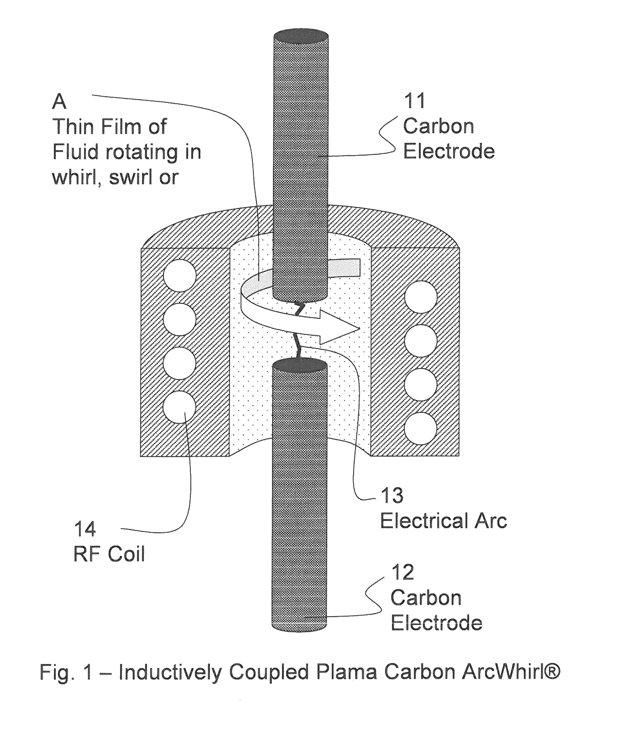
[0110]Referring again to FIG. 2, the RF coil assembly 14 is placed around the ArcWhirl® Torch 10. This now converts the ArcWhirl® into an Inductively Coupled Plasma Torch. By selecting the proper frequency either or both of the carbon rods or the plasma can be coupled to the electrical field created by the radio frequency. Natural Gas from the well is flowed directly into fluid inlet 15. The ICP ArcWhirl® Torch 10 is ignited by dead shorting the carbon rods then pulling them back. The vortex created by the natural gas confines the plasma arc using inertia. Next, the RF coil 14 is turned on which increases the plasma volume. As the natural gas cracks into carbon and hydrogen the carbon will continue heating due to the RF field. This ensures that all of the natural gas is cracked into hydrogen and carbon.

[0111]Since the ArcWhirl® is a cyclone separator it can be configured and modified by means known in the art to separate the hydrogen from the carbon. This new means of generating hyd...

example 3

[0112]Turning now to FIG. 3, the ICP ArcWhirl®10 Reactor can easily be assembled in modules. A standard ArcWhirl® Torch as disclosed in U.S. Pat. Nos. 7,422,695 and 7,578,937 and U.S. Published Patent Application No. US20090235637, entitled, “SYSTEM, METHOD AND APPARATUS FOR LEAN COMBUSTION WITH PLASMA FROM AN ELECTRICAL ARC” is the first module. It is attached by means know in the art to the RF Coil Module 14. The RF Coil Module 14 includes one or more slits or inlets 17 to introduce a material such as a solid, liquid or gas for treatment purposes. This configuration allows for treating of two separate materials with one apparatus.

[0113]This modular system allows for a compact and easy to assemble plasma chemical reactor for treating two separate materials comprising: a vessel 14 having an interior defined by a cylindrical portion disposed between a first end and a second end, an outlet in said second end that is aligned with a longitudinal axis of the cylindrical portion, and an i...


PUM

PropertyMeasurementUnit
lengthaaaaaaaaaa
diameteraaaaaaaaaa
Temperatureaaaaaaaaaa

Abstract

A plasma system includes a plasma arc torch, a cylindrical tube and an eductor. The plasma arc torch includes a cylindrical vessel having a first end and a second end, a first tangential inlet / outlet connected to or proximate to the first end, a second tangential inlet / outlet connected to or proximate to the second end, an electrode housing connected to the first end such that a first electrode is (a) aligned with a longitudinal axis of the cylindrical vessel, and (b) extends into the cylindrical vessel, and a hollow electrode nozzle connected to the second end of the cylindrical vessel. The cylindrical tube is attached to the hollow electrode nozzle and aligned with the longitudinal axis, the cylindrical tube having a side inlet and a radio frequency coil disposed around or embedded within the cylindrical tube. The eductor is attached to the cylindrical tube and aligned with the longitudinal axis.

Description

FIELD OF THE INVENTION[0001]The present invention relates generally to the field of plasma confinement, and more particularly, to a system, method and apparatus for creating, confining and sustaining a dense inductively coupled plasma arc whirl.PRIORITY CLAIM AND CROSS-REFERENCE TO RELATED APPLICATIONS[0002]This patent application is related to: This patent application is (a) a non-provisional application of U.S. patent application 61 / 787,682 filed on Mar. 15, 2013, and entitled “System, Method and Apparatus for Creating, Confining and Sustaining a Dense Inductively Coupled Plasma Arc Whirl”, (b) a non-provisional application of U.S. patent application 61 / 788,244 filed on Mar. 15, 2013, and entitled “Plasma Whirl Reactor Apparatus and Methods of Use”, and (c) a continuation-in-part application of U.S. patent application Ser. No. 13 / 633,128 filed on Oct. 1, 2012, entitled “Plasma Arc Torch Having Multiple Operating Modes”, which is a continuation-in-part application of U.S. patent ap...

Claims


Application Information

Patent Timeline
Patent Type & Authority Patents(United States)
IPC IPC(8): H01J17/26F02K3/08B23K15/08H05H1/48H05H1/30B23K15/06B23K15/00B23K10/02H05H1/34B23K10/00H05H1/44H05H1/40
CPCH05H1/40B23K10/00B23K10/006B23K10/02B23K15/0046B23K15/06B23K15/08F02K3/08H05H1/30H05H1/34H05H1/44H05H1/48H01J2237/31H05H2001/3431H05H2001/3484H05H1/3431H05H1/3484B01J12/002
Inventor FORET, TODD
Owner FORET PLASMA LABS
Learn More