Device for increasing heat transfer

a technology of heat sink and heat sink, which is applied in the direction of insulated conductors, power cables, cables, etc., can solve the problems of generating disturbing noise, affecting the operation of equipment, and requiring a large amount of space for the heat sink, so as to achieve the effect of not disturbing the surroundings

Inactive Publication Date: 2001-06-26
UNWIRED PLANET
View PDF14 Cites 94 Cited by
  • Summary
  • Abstract
  • Description
  • Claims
  • Application Information

AI Technical Summary

Benefits of technology

The problem stated above can be solved in more detail according to the following. The means to affect the air motion comprises one or more nozzles with flow resistances depending upon the direction of the flow. The nozzle (nozzles) causes a net flow of air through the nozzle, whereby the device is arranged to take advantage of the net flow of air, to obtain the continuous exchange of air surrounding the object. The object is, for example, a heat sink which, for example, is used for cooling electronics or something else. A

Problems solved by technology

However, the heat sink usually requires a relatively large amount of space, which of course is a disadvantage for such technical equipment that cannot take a lot of room.
However, the fans have a disadvantage in that they generate disturbing noise.
The fans have another disadvantage in that they require maintenance, for example due to lubricant in the bearings of the fans getting old and therefore must be replaced at certain time intervals.
The

Method used


Image

  • Device for increasing heat transfer
  • Device for increasing heat transfer
  • Device for increasing heat transfer

Examples


Embodiment Construction

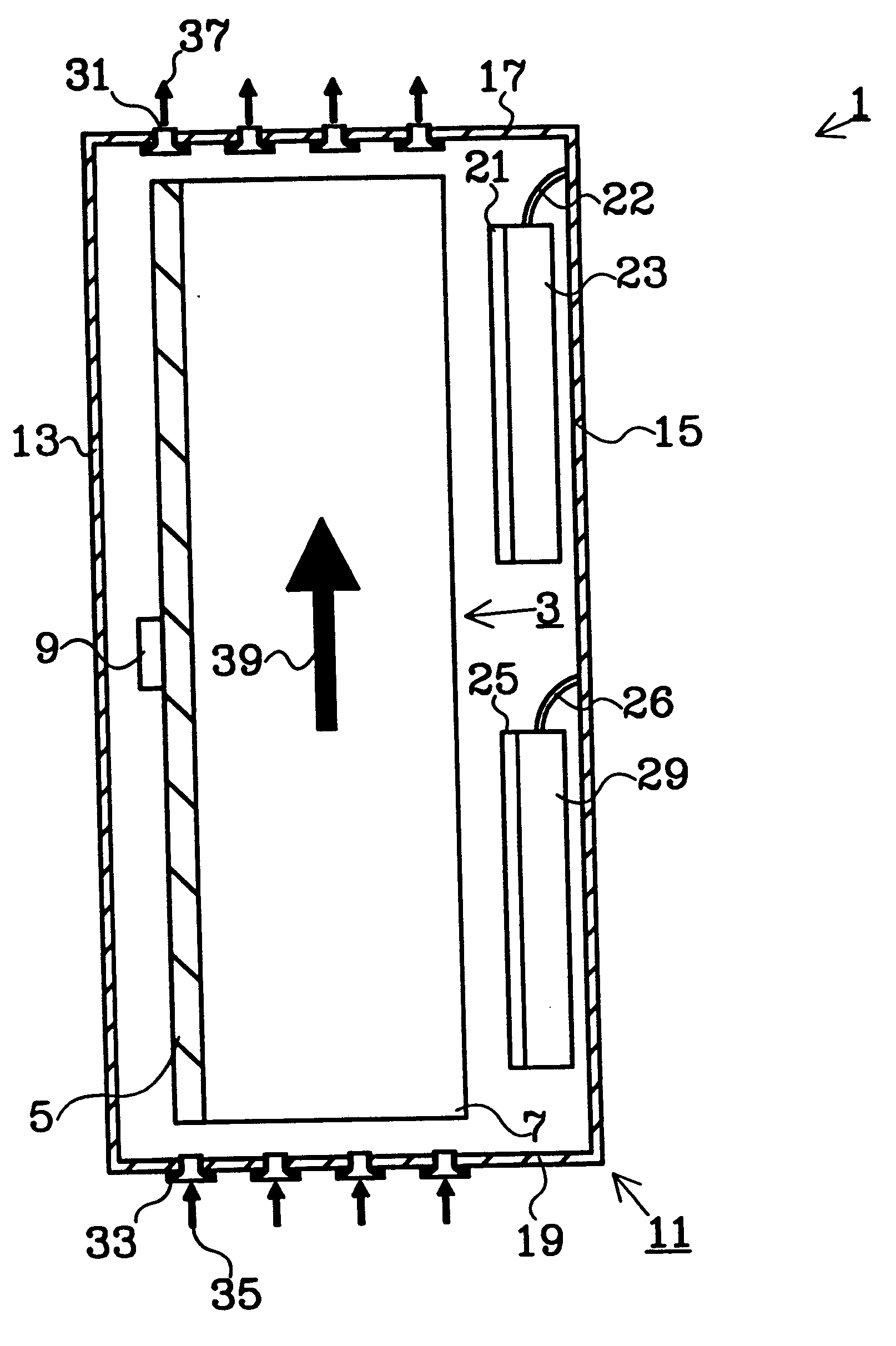
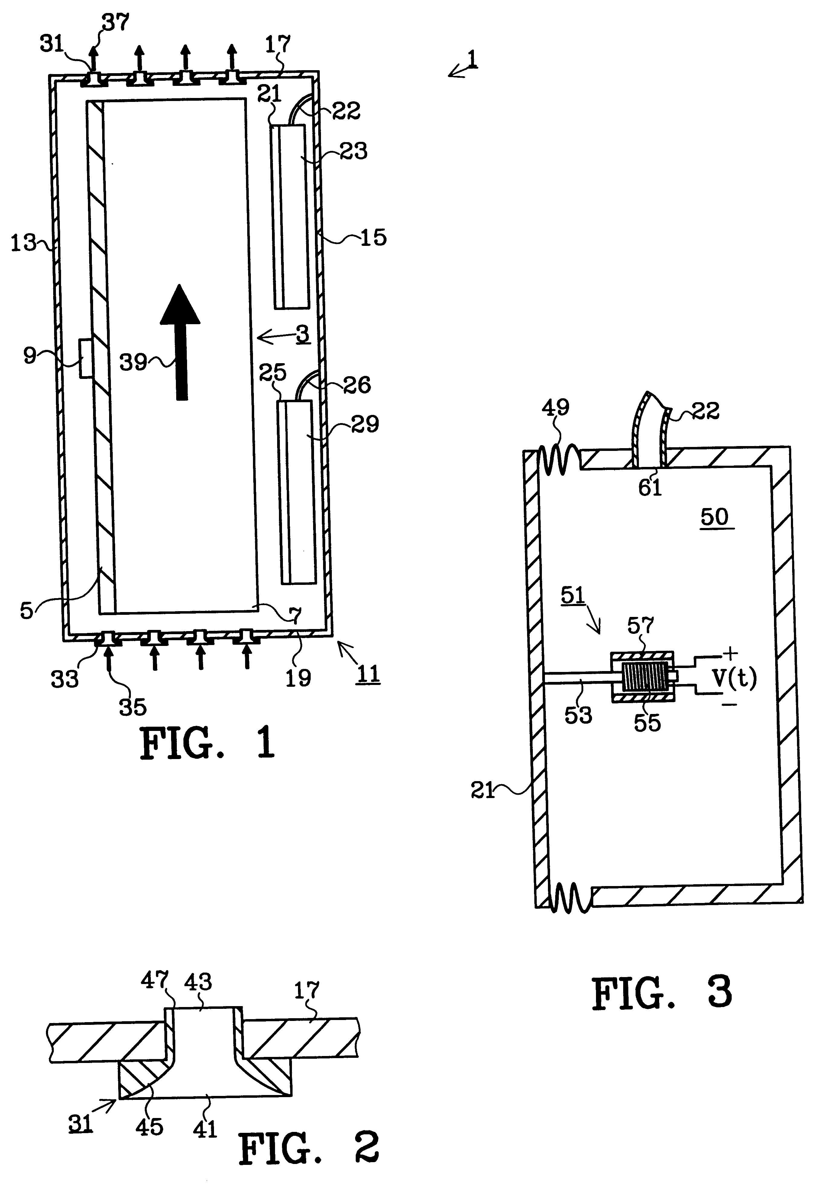
FIG. 1 shows, in a sectional view, as an example according to the invention, a first device 1 for increasing the heat transfer from a heat sink 3 to air surrounding the heat sink 3.

The heat sink 3 in FIG. 1 comprises a ground plate 5 with good thermal conductivity on which electronics 9 that is to be cooled is arranged. The expression "electronics" comprises here all kinds of electronic equipment, such as electronic components, electronic circuits, radio equipment, microwave equipment, etc. Further, the heat sink comprises a predetermined number of heat dissipators in the form of cooling flanges 7, which are arranged on the ground plate 5 on the opposite side of the electronics 9. Of course, the invention is not limited to only this kind of heat sink 3; rather the person skilled in the art has the possibility, according to the circumstances and his / her own desire, to arrange this in another way. The heat sink 3 is arranged in a space in a cabinet 11, which in the example shown in FI...


PUM


Abstract

A device for increasing heat transfer from an object includes at least one oscillating membrane for generating air motion in air surrounding the object, and a nozzle for affecting the air motion so that the air motion causes a continuous exchange of the air surrounding the object.

Description

This application claims priority under 35 U.S.C. .sctn..sctn.119 and / or 365 to 9804299-7 filed in Sweden on Dec. 11, 1998; the entire content of which is hereby incorporated by reference.The present invention relates to the field of devices for increasing the heat transfer from an object.DESCRIPTION OF PRIOR ARTTechnical equipment often comprises electronics (or other objects) which needs to be cooled, on one hand to prevent the electronics and other adjacent equipment from being overheated, on the other hand to prevent persons who come into contact with the technical equipment from getting burned.One way of cooling the electronics is to arrange the electronics in a good thermal contact with a heat sink, which has a relatively large heat transferring surface from which heat is transferred to the surroundings (e.g. surrounding air). The heat sink is usually made of a material with relatively good thermal conductivity and usually comprises heat dissipators, such as cooling flanges or ...

Claims


Application Information

Patent Timeline
IPC IPC(8): F04B35/00F04B35/04F28F13/00F28F13/10H01L21/02H01L21/467H05K7/20
CPCF04B35/045F28F13/10H01L21/467H05K7/20172H05K7/20
Inventor TULLSTEDT, CARL HENRIKBERGMAN, PATRIKEDGREN, ANDERS
Owner UNWIRED PLANET
Why Eureka
Try Eureka