Method of broad band electromagnetic holographic imaging

a broad band electromagnetic and holographic imaging technology, applied in the field of broad band electromagnetic holographic imaging, can solve the problems of limited success in developing a method for quickly interpreting geophysical em data over two-dimensional geoelectrical structures, and not pointed to a practical useful method for accomplishing broad band em imaging of three-dimensional objects in non-transparent media, and achieves simple hardware arrangement and simple software

Inactive Publication Date: 2001-06-26
THE UNIV OF UTAH
View PDF17 Cites 81 Cited by
  • Summary
  • Abstract
  • Description
  • Claims
  • Application Information

AI Technical Summary

Benefits of technology

An imaging apparatus, capable of performing in real time in accordance with the method of this invention for broad band EM holographic imaging requires a relatively simple hardware arrangement and simple software.

Problems solved by technology

This reference wave is coherent with the object light and interferes with it, producing diffraction patterns which form an optical hologram on the photographic emulsion.
These earlier efforts to develop a method for quickly interpreting geophysical EM data over two-dimensional geoelectrical structures have met with limited success.
Moreover, they have not pointed towards a practically useful method for accomplishing broad band EM imaging of three-dimensional objects in nontransparent media.

Method used


Image

  • Method of broad band electromagnetic holographic imaging
  • Method of broad band electromagnetic holographic imaging
  • Method of broad band electromagnetic holographic imaging

Examples


example 1

The following explanation of the principles of broad band EM holographic imaging reconstruction is offered to assist those skilled in the art to practice the invention. It is not intended thereby to limit the scope of the invention to any particular theory of operation or to any field of application.

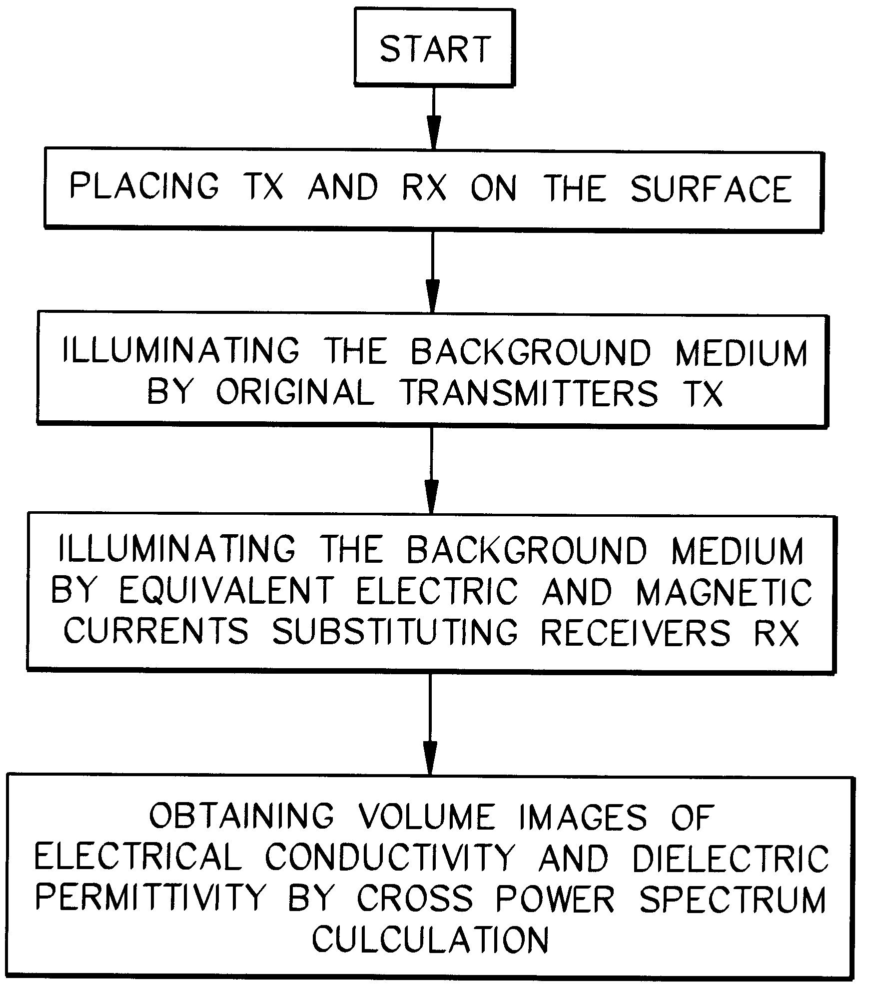
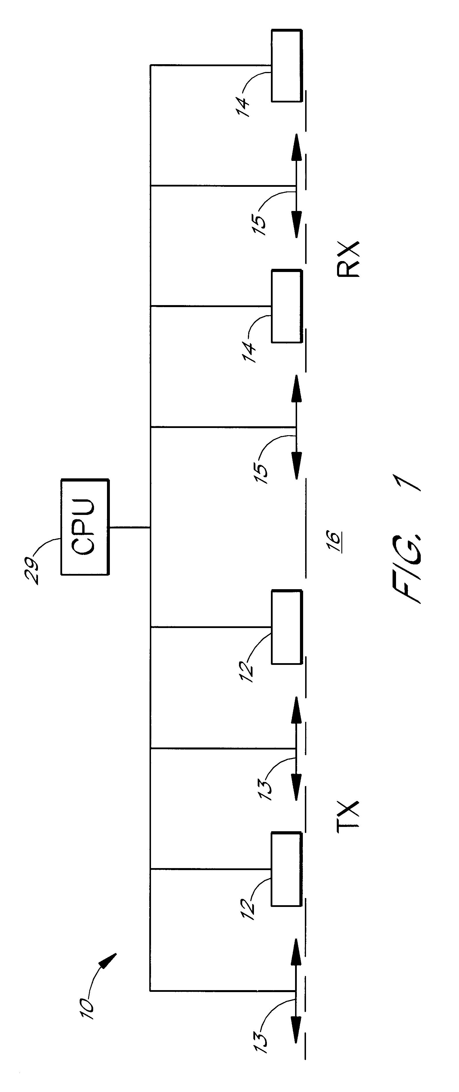
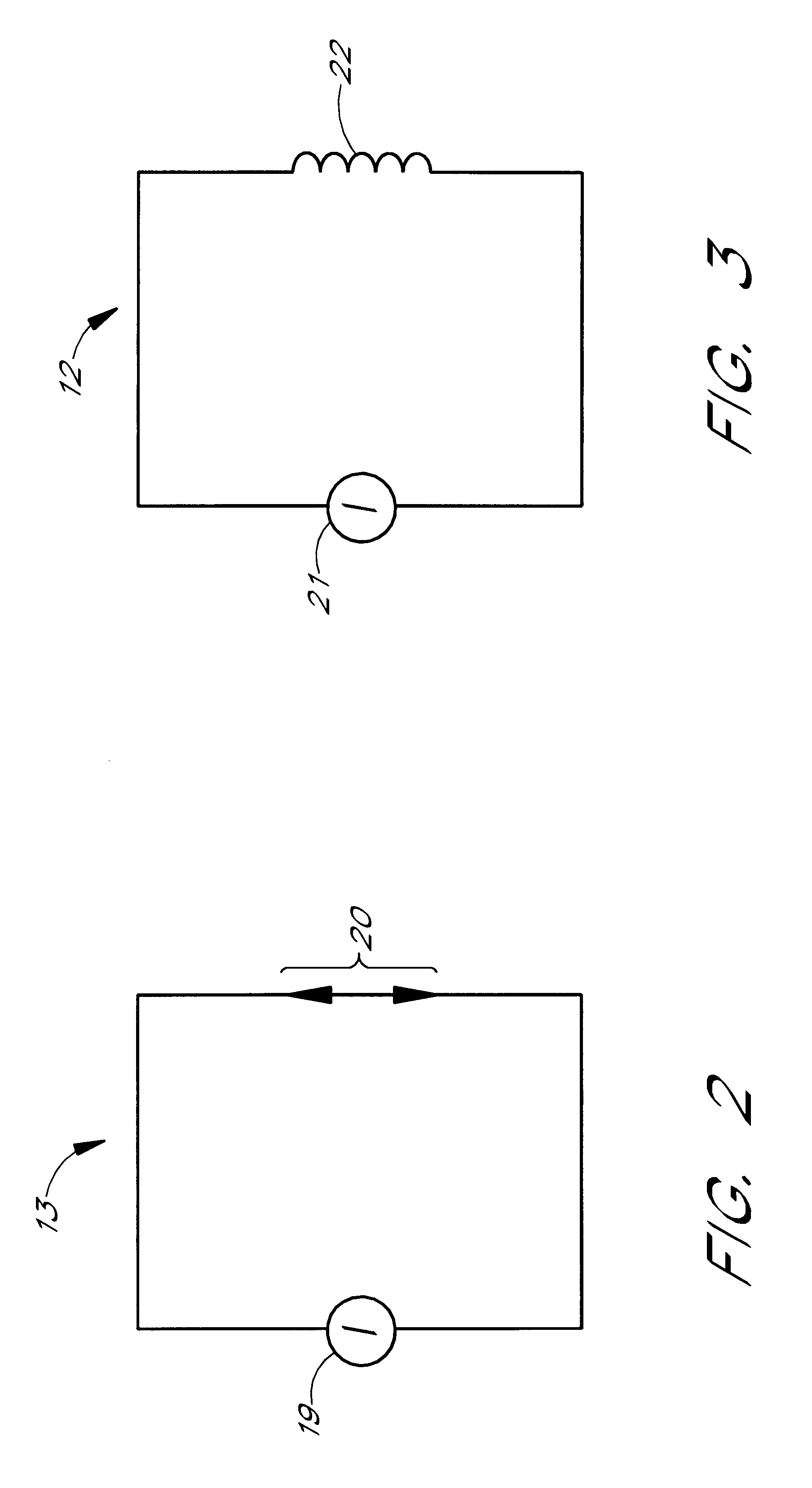
A three dimensional inhomogeneous medium, with a known background complex conductivity, .sigma..sub.b, contains a local inhomogeneous object D with an arbitrarily varying complex conductivity .sigma.=.sigma..sub.b +.sigma..sub.a. The location of D and its anomalous conductivity .sigma..sub.a, are unknown. The examined medium is considered to be non-magnetic, and hence .mu.=.mu..sub.0 =4.pi..times.10.sup.-7 H / m, where .mu. is the magnetic permeability and .mu..sub.0 is the free-space magnetic permeability. The model is excited by an EM field generated by a given system of sources (transmitters TX) with an electric current density j.sup.e. This field is time harmonic as e.sup.-i.omega.t an...

example 2

The image generating method of the present invention solves the minimum energy flow problem for the residual field {E.sup.66 ,H.sup.66 } computed as the difference between the observed field {E.sub.obs,H.sub.obs } and numerically calculated (predicted) field {E.sub.pr,H.sub.pr } for a constructed image.

The energy flow of the residual electromagnetic field can be calculated using the complex Poynting vector P, introduced by the formula:

P=1 / 2E.sup.66 .times.H.sup..DELTA. *. (3)

which is known to be a non-negative function.

The measure .PHI. of the difference between the observed and predicted fields can be introduced as the energy flow of the residual field through the surfaces of observations, integrated over the frequency .omega.:

The theoretical predicted fields E.sub.pr, (r,.omega.), H.sub.pr, (r,.omega.) depend on the sum of the background .sigma..sub.b (r) and anomalous conductivity distribution .sigma..sub.a (r) in the examined

.PHI.=Re.intg..sub.106 .intg..intg..sub.S P.multidot.n...

example 3

It is possible to improve the resolution of imaging by repeating the steps of the previous examples iteratively. This procedure solves the inverse problem for determination of the material properties and location of the target.

The general iterative process can be described by the formula:

.sigma..sub.a(n+1) (r)=.sigma..sub.a(n) (r)+k.sub.n A.sub.n (r)-i.omega.B.sub.n (r), (25)

where n=1,2,3, . . . ,N; k.sub.l =k; A.sub.1 (r)=A(r), B.sub.1 (r)=B(r); and .sigma..sub.a(1) (r)=.sigma..sub.a (r)-i.omega..epsilon..sub.a (r)=kA(r)-i.omega.kB(r).

The cross power spectra on the n-th iteration A.sub.n (r) and B.sub.n (r) can be calculated by formulae, analogous to (10) and (11) in the frequency domain:

A.sub.n (r)=Re .intg. .OMEGA.E.sub.n.sup.b (r, .omega.).multidot.E.sub.n.sup.a (r, .omega.) d.omega.,

B.sub.n (r)=Re .intg. .OMEGA.(-i.omega.) E.sub.n.sup.b (r, .omega.).multidot.E.sub.n.sup.a (r, .omega.) d.omega., (26)

where E.sub.n.sup.b (r, .omega.) is the corrected background field calculated by...


PUM

PropertyMeasurementUnit
electromagneticaaaaaaaaaa
electromagnetic fieldaaaaaaaaaa
cross poweraaaaaaaaaa

Abstract

A method of imaging an object, such as a diseased human heart or bone, in a nontransparent medium, such as the human body, involves placing an array of transmitters and receivers in operational association with the medium. The transmitters generate a harmonic (frequency domain) or pulse (time domain) primary electromagnetic field (EM) which propagates through the medium. The primary field interacts with the object to produce a scattered field, which is recorded by the receivers. The scattered EM field components measured by the receivers are applied as an artificial EM field to generate a backscattering EM field. Cross power spectra of the primary and backscattering fields (in the frequency domain) or cross correlation between these fields (in the time domain) produce a numerical reconstruction of an EM hologram. The desired properties of the medium, such as conductivity or dielectric permittivity, are then derived from this hologram.

Description

This invention relates to three dimensional ("holographic") imaging. It is specifically directed to the electromagnetic (EM) imaging of an object within a non-transparent medium. It provides methodology and apparatus for conducting nondestructive and / or non-invasive inspections, utilizing broad band electromagnetic signals.Conventional optical holography constructs a volume (three dimensional) image of an object by displaying the amplitude and the phase structure of a wavefront of light. A reference wave of light is relied upon to facilitate the recording of both the amplitude and the phase condition of the object light by means of photographic emulsion. This reference wave is coherent with the object light and interferes with it, producing diffraction patterns which form an optical hologram on the photographic emulsion. To generate a volume image, this optical hologram need merely be illuminated with a reference light wave. The resulting diffraction pattern wave (as scattered by th...

Claims


Application Information

Patent Timeline
Patent Type & Authority Patents(United States)
IPC IPC(8): G03H1/04A61B5/05A61B10/00G01N22/02G01S13/89G03H5/00
CPCA61B5/417G03H1/04A61B5/05
Inventor ZHDANOV, MICHAEL S.
Owner THE UNIV OF UTAH
Why Eureka
Try Eureka