Medical broad band electromagnetic holographic imaging
Inactive Publication Date: 2005-04-05
UNIV OF UTAH RES FOUND
View PDF23 Cites 28 Cited by
Summary
Abstract
Description
Claims
Application Information
AI Technical Summary
This helps you quickly interpret patents by identifying the three key elements:
Problems solved by technology
Method used
Benefits of technology
Benefits of technology
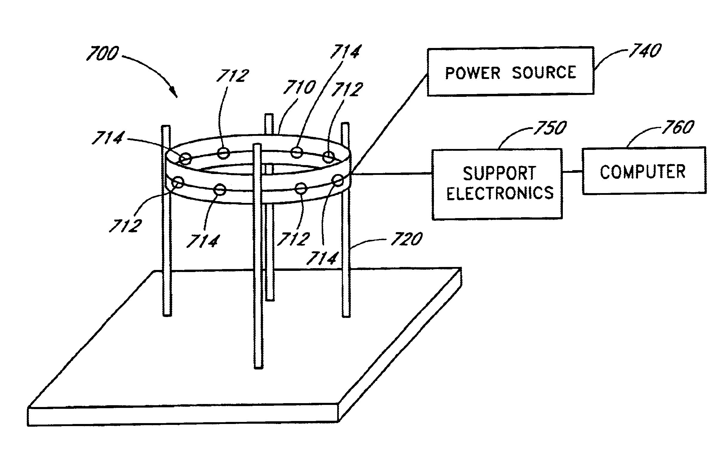
An imaging apparatus, capable of performing in real time in accordance with the described method for broad band EM holographic imaging requires a relatively simple hardware arrangement and simple software.
These earlier efforts to develop a method for quickly interpreting geophysical EM data over two-dimensional geoelectrical structures have met with limited success.
Moreover, they have not pointed towards a practically useful method for accomplishing broad band EM imaging of three-dimensional objects in nontransparent media.
Method used
Image
Click on the blue label to locate the original text in one second.
Reading with bidirectional positioning of images and text.
Examples
example 1
The following explanation of the principles of broad band EM holographic imaging reconstruction is offered to assist those skilled in the art to practice the invention. It is not intended thereby to limit the scope of the invention to any particular theory of operation or to any field of application.
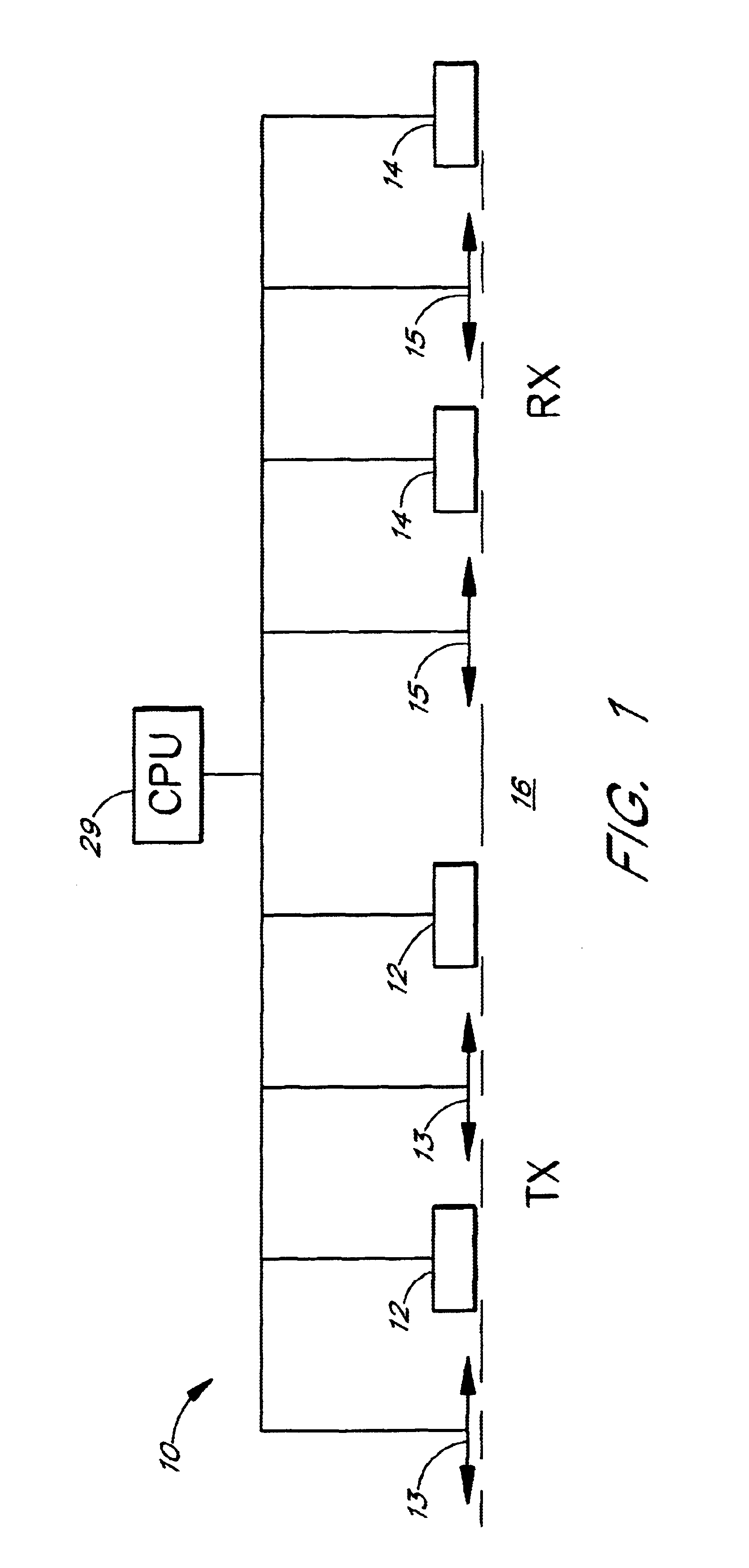
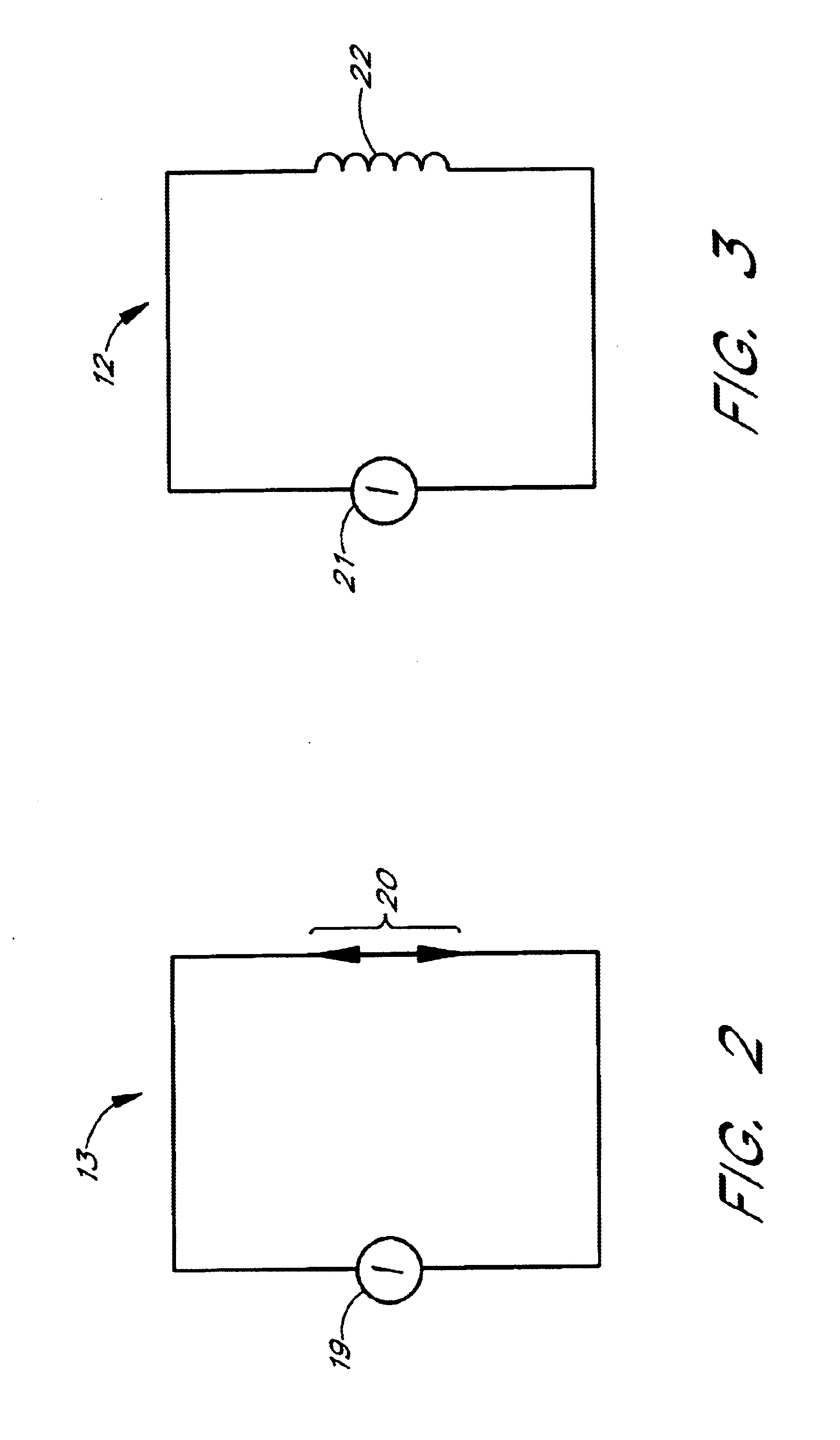
A three dimensional inhomogeneous medium, with a known background complex conductivity, b, contains a local inhomogeneous object D with an arbitrarily varying complex conductivity =b+a. The location of D and its anomalous conductivity a, are unknown. The examined medium is considered to be non-magnetic, and hence μ=μ0=4π×10−7 H / m, where μ is the magnetic permeability and μ0 is the free-space magnetic permeability. The model is excited by an EM field generated by a given system of sources (transmitters TX) with an electric current density je. This field is time harmonic as e−iωt and is observed by the system of receivers RX located on the surface S of the examined medium. Complex conducti...
example 2
The image generating method solves the minimum energy flow problem for the residual field {EΔ, HΔ} computed as the difference between the observed field {Eobs, Hobs} and numerically calculated (predicted) field {Epr, Hpr} for a constructed image.
The energy flow of the residual electromagnetic field can be calculated using the complex Poynting vector P, introduced by the formula: P=12EΔ×HΔ*.(3)
which is known to be a non-negative function.
The measure Φ of the difference between the observed and predicted fields can be introduced as the energy flow of the residual field through the surfaces of observations, integrated over the frequency ω:
The theoretical predicted fields Epr (r, ω), Hpr (r, ω) depend on the sum of the background b (r) and anomalous conductivity distribution a (r) in the examined Φ=Re∫Ω∫∫SP·n ⅆsⅆω=12Re∫Ω∫∫S[EΔ(r,ω)×HΔ*(r,ω)]·nⅆsⅆω(4)
medium, and, therefore, the residual field energy flow φ is a function of [b(r)+a(r)]:
φ=φ[b+a]. (5)
It can be expressed ap...
example 3
It is possible to improve the resolution of imaging by repeating the steps of the previous examples iteratively. This procedure solves the inverse problem for determination of the material properties and location of the target.
The general iterative process can be described by the formula:
a(n+1)(r)=a(n)(r)+knAn(r)−iωBn(r) (25)
where n=1, 2, 3, . . . , N; k1=k; A1(r)=A(r), B1(r)=B(r); and a(1)(r)=σa(r)−iωkB(r)=kA(r)−iωkB(r).
The cross power spectra on the n-th iteration An(r) an dBn(r) can be calculated by formulae, analogous to (1) and (11) in the frequency domain:
An(r)=Re∫ΩEnb(r, ω)·Ena(r, ω)dω,
Bn(r)=Re∫Ω(−iω)Enb(r, ω)·Enb(r, ω)dω, (26)
where Enb(r, ω) is the corrected background field calculated by forward modeling for the geoelectrical model with the corrected background conductivity distribution b(n)=a(n)+a(n), and En8(r, ω), is the corrected backscattering field of the corrected residual field EΔn, which is the difference between the observed field and the corrected backgrou...
PUM
Abstract
A method of imaging an object, such as a diseased human heart or bone or malignant tumor, in a nontransparent medium, such as the human body, involves placing an array of transmitters and receivers in operational association with the medium. The transmitters generate a broad bandharmonic (frequency domain) or pulse (time domain) primary electromagnetic field (EM) field, including the lower frequency portions of the EM spectrum, whose propagation is typically characterized by the diffusion phenomena, or by the combination of the diffusion and wave phenomena. The primary field propagates through the examined medium and interacts with the object to produce a scattered field, which is recorded by the receivers. The scattered EM field components measured by the receivers are applied as an artificial EM field to generate a backscattering EM field. Cross power spectra of the primary and backscattering fields (in the frequency domain) or cross correlation between these fields (in the time domain) produce a numerical reconstruction of an EM hologram. The desired properties of the medium, such as conductivity or dielectricpermittivity, are then derived from this hologram.
Description
FIELD OF THE INVENTIONThis invention relates to three dimensional (“holographic”) imaging. It is specifically directed to the electromagnetic (EM) imaging of an object within a non-transparent medium. It provides methodology and apparatus for conducting nondestructive and / or non-invasive inspections, utilizing broad band electromagnetic signals.BACKGROUND OF THE INVENTIONConventional optical holography constructs a volume (three dimensional) image of an object by displaying the amplitude and the phase structure of a wavefront of light. A reference wave of light is relied upon to facilitate the recording of both the amplitude and the phase condition of the object light by means of photographic emulsion. This reference wave is coherent with the object light and interferes with it, producing diffraction patterns which form an optical hologram on the photographic emulsion. To generate a volume image, this optical hologram need merely be illuminated with a reference light wave. The resul...
Claims
Application Information
Patent Timeline
Application Date:The date an application was filed.
Publication Date:The date a patent or application was officially published.
First Publication Date:The earliest publication date of a patent with the same application number.
Issue Date:Publication date of the patent grant document.
PCT Entry Date:The Entry date of PCT National Phase.
Estimated Expiry Date:The statutory expiry date of a patent right according to the Patent Law, and it is the longest term of protection that the patent right can achieve without the termination of the patent right due to other reasons(Term extension factor has been taken into account ).
Invalid Date:Actual expiry date is based on effective date or publication date of legal transaction data of invalid patent.

