Shift register

a technology of shift register and shift register, which is applied in the direction of logic circuit coupling/interface arrangement, digital storage, instruments, etc., can solve the problems of large amount of time required to insert even one data, and requires a long processing time to delete specific data from a held data string, etc., to achieve simple hardware arrangement and quick and easy operation

Inactive Publication Date: 2005-06-07
NEC CORP
View PDF8 Cites 0 Cited by
  • Summary
  • Abstract
  • Description
  • Claims
  • Application Information

AI Technical Summary

Benefits of technology

[0005]It is an object of the present invention to provide a shift register which can quickly and easily perform operation with respect to a data string like inserting data in the data string and deleting data from the data string by using a simple hardware arrangement.

Problems solved by technology

A large amount of time is therefore required to insert even one data.
Although the shift register disclosed in reference 1 can quickly and easily insert data into a data string, it requires a long processing time to delete specific data from a held data string.

Method used


Image

  • Shift register
  • Shift register
  • Shift register

Examples


first embodiment

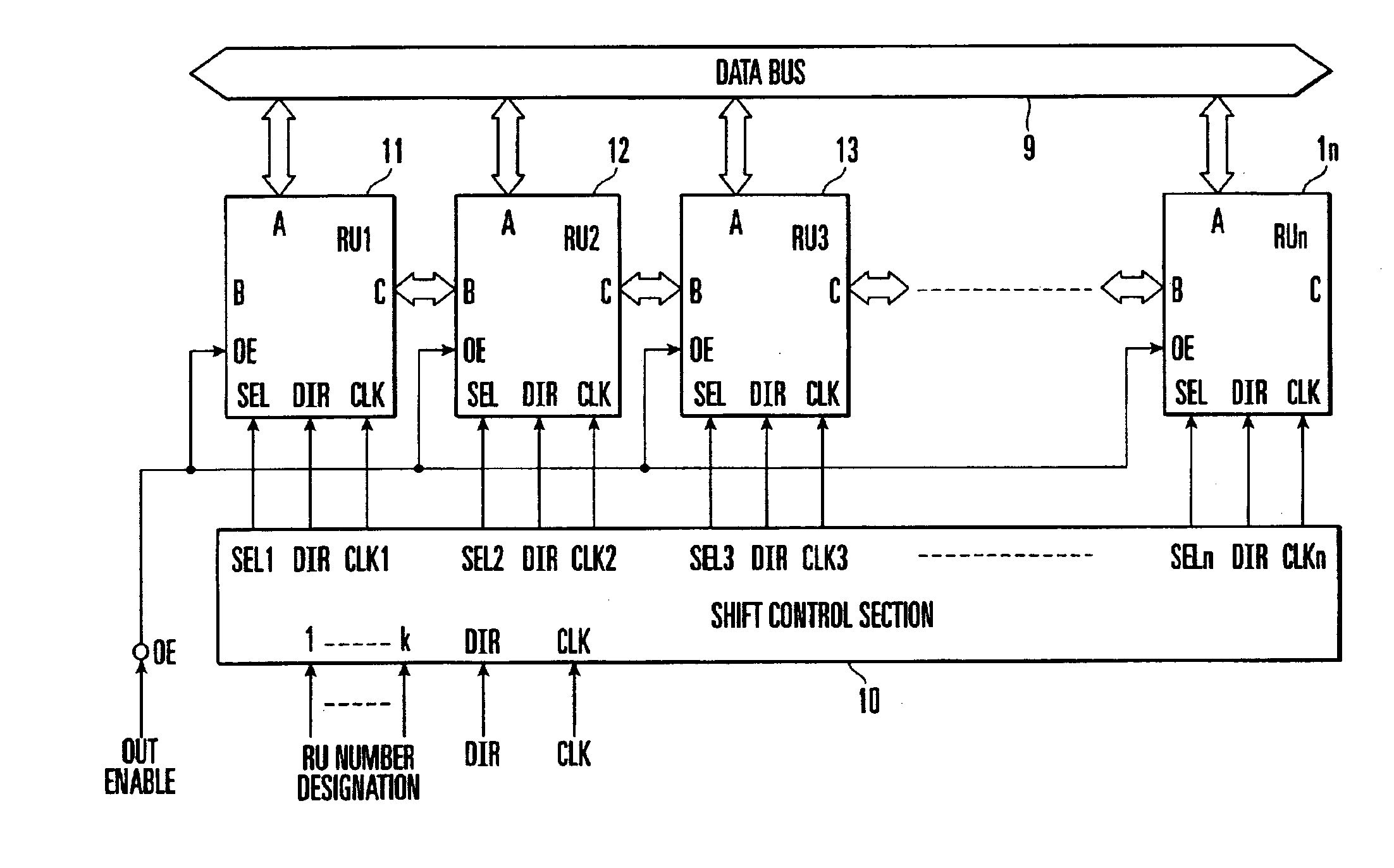
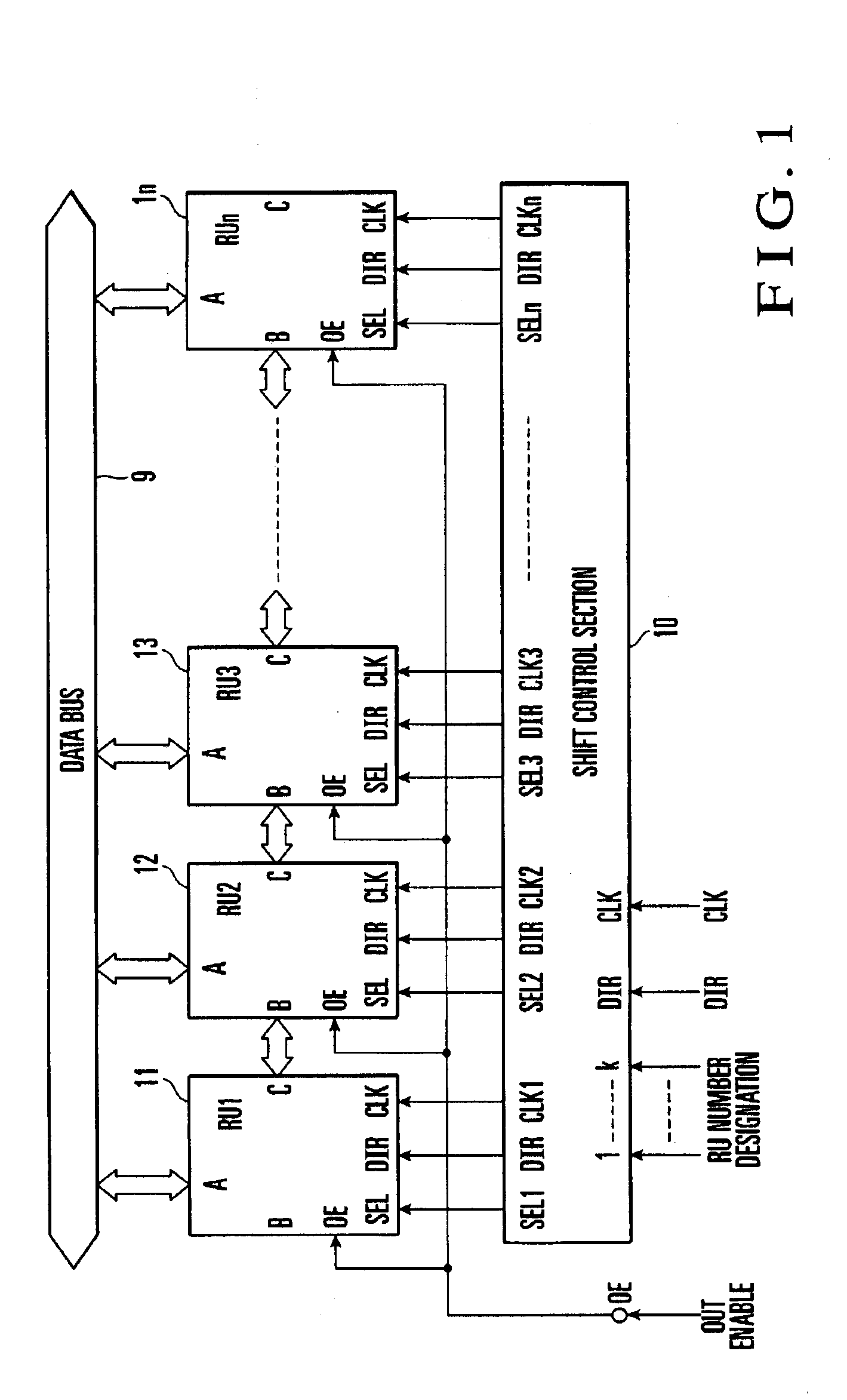
[0014]FIG. 1 shows a shift register according to the present invention. The shift register according to this embodiment is comprised of n (n is a natural number equal to or more than 2) cascaded bidirectional register units (RUs) 11 to 1n and a shift control section 10 for controlling the bidirectional register units 11 to 1n.

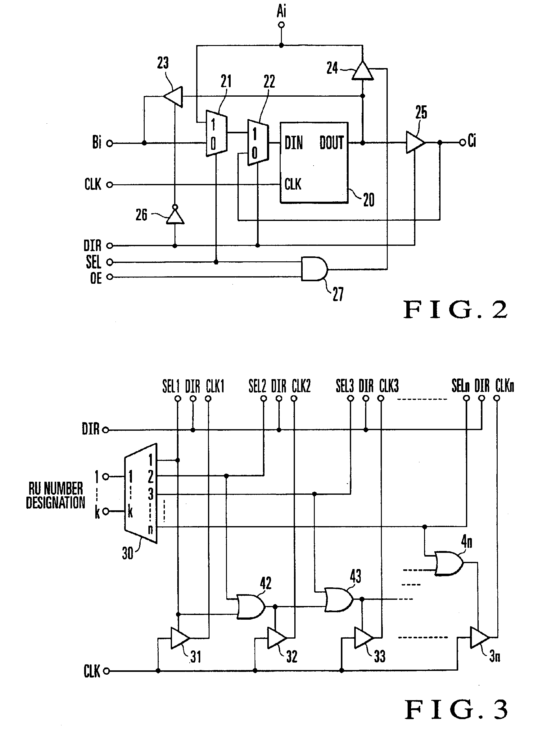
[0015]Each of the bidirectional register units 11 to 1n includes an m-bit (m is a natural number) input / output terminal (direct input / output terminal) A capable of parallelly inputting / outputting data from / to a data bus 9 having a m-bit bus width, an m-bit input / output terminal (preceding-stage shifting input / output terminal) B for parallelly inputting / outputting data to / from the preceding-stage bidirectional register unit, and an m-bit input / output terminal (subsequent-stage shifting input / output terminal) C for parallelly inputting / outputting data to / from the subsequent-stage bidirectional register unit. Each of the bidirectional register units 11 to 1n also...

second embodiment

[0052]With this operation, up to which register unit data has been set (inserted) can be quickly known from address information from the priority encoder 70. This makes it possible to quickly detect the location of new data added to the end of a data string as in the Without a means like that in this embodiment, for example, a means for recording, on a memory or the like, information indicating up to which bidirectional register unit data has been set is required, resulting in complicated processing.

[0053]As has been described above, according to the present invention, operation with respect to a data string like inserting and deleting data with respect to the data string stored in a group of bidirectional register units can be easily and quickly implemented on hardware.

[0054]In addition, each bidirectional register unit is constituted by a plurality of bidirectional registers, and shift clocks are synchronously applied to these bidirectional registers. In addition, input / output op...


PUM


Abstract

A shift register includes bidirectional register units, a direction switching section, a register unit selecting section, and a shift clock supply section. The bidirectional register units are cascaded through first input/output terminals for data shifting and perform data shifting operation. The bidirectional register units have second input/output terminals which separately and directly input/output data. The direction switching section switches the shifting directions of the bidirectional register units. The register unit selecting section selects one of the bidirectional register units and inputs/outputs data through the second input/output terminal. The shift clock supply section supplies shift clocks to the bidirectional register units ranging from the bidirectional register unit selected by the register unit selecting section to the last-stage bidirectional register unit.

Description

BACKGROUND OF THE INVENTION[0001]The present invention relates to a shift register formed by cascading a plurality of bidirectional register units and, more particularly, to a shift register which can quickly perform processing such as inserting and deleting data with respect to a held data string.[0002]In order to orderly organize data in a communication device or the like by rearranging the data in chronological order or address order, some operation is required for a data string. Conventionally, such a function has been implemented by software processing. For example, new data is generally inserted into a data string by a technique of using a program to shift data located behind the insertion location of the new data one by one and inserting the new data into the resultant free space. A large amount of time is therefore required to insert even one data.[0003]In order to solve this problem, the present inventor has proposed a shift register in Japanese Patent Laid-Open No. 2001-12...

Claims


Application Information

Patent Timeline
Patent Type & Authority Patents(United States)
IPC IPC(8): G11C19/28G11C19/00H03K19/0175
CPCG11C19/28G11C19/00
Inventor NAKAMURA, MITSUYUKI
Owner NEC CORP
Why Eureka
Try Eureka