
Ambient humidity measurement using microwaves

a microwave and ambient humidity technology, applied in direction finders using radio waves, instruments, mechanical means, etc., can solve the problems of low measurement accuracy of humidity sensors, difficult to achieve long term ambient humidity measurement with any high degree of accuracy or reliability, and high maintenance costs of humidity sensors

Inactive Publication Date: 2001-07-10
LUCENT TECH INC
View PDF13 Cites 22 Cited by
  • Summary
  • Abstract
  • Description
  • Claims
  • Application Information

AI Technical Summary

Problems solved by technology

Long term ambient humidity measurement is difficult to achieve with any high degree of accuracy or reliability.
Such humidity sensors typically exhibit low measurement accuracy, particularly at the extremes of 0-20% and 80-100% humidity.
Humidity sensors having higher accuracy exist, but typically at the cost of higher maintenance and short accuracy lifetimes in the field.
However, such higher accuracy humidity sensors , including lithium chloride and wet / dry bulb automated, are typically expensive to manufacture and require rigid and frequent maintenance (e.g., to clean the mirror).
While solid state humidity sensors are reasonably priced and accurate, they have been known to fail or degrade fairly quickly (e.g., after about 1 year or so), and thus tend to be both inaccurate and somewhat unreliable after a period of time.

Method used


Image

  • Ambient humidity measurement using microwaves
  • Ambient humidity measurement using microwaves

Examples


Embodiment Construction

The present invention provides the ability to accurately measure ambient humidity at a reasonable cost without the need for delicate moving parts, requiring minimal if any maintenance, and without the need for components which would degrade significantly over time.

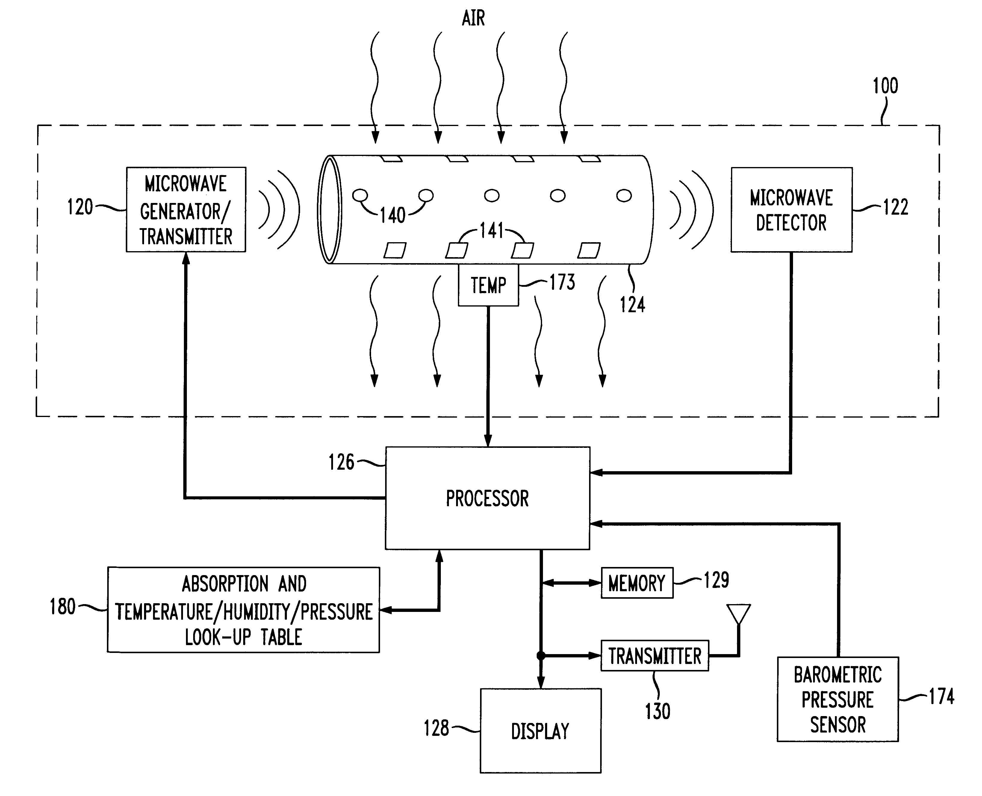
In accordance with the principles of the present invention, the absorbency of microwave transmissions through a shielded structure such as a metal tube is measured and related directly to the humidity in ambient air passed through the tube.

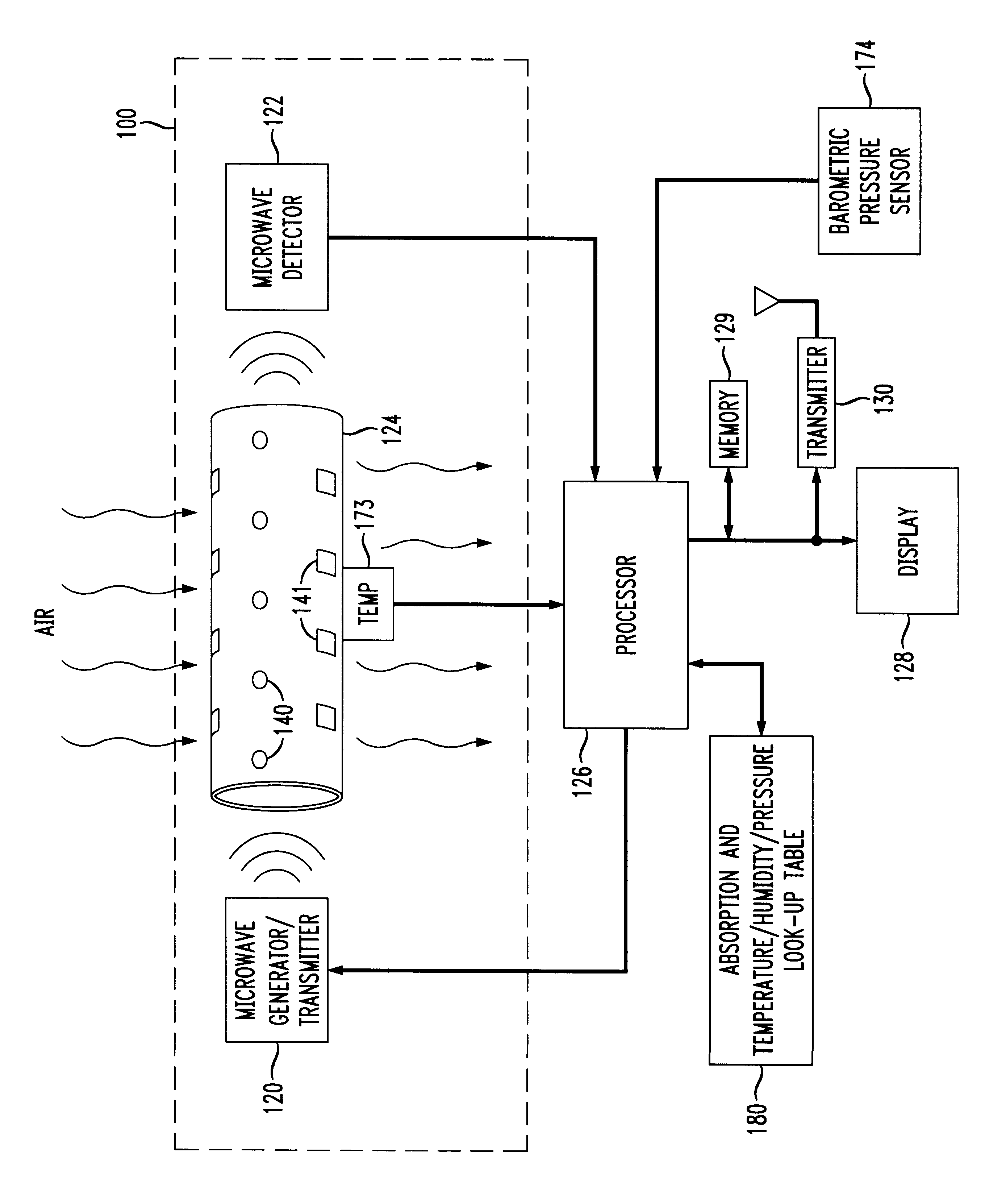
FIG. 1 shows a block diagram of an exemplary microwave humidity sensor constructed in accordance with the principles of the present invention.

In particular, in FIG. 1, the basis of a microwave humidity sensor 100 is formed by a microwave generator / transmitter 120 fixed to one end of a metal structure 124 capable of containing an amount of microwave energy traversing an internal length thereof. The metal structure 124 includes a number of holes 140, 141 allowing passage of ambient air the...


PUM

PropertyMeasurementUnit
humidityaaaaaaaaaa
humidityaaaaaaaaaa
humidityaaaaaaaaaa

Abstract

A humidity sensor which utilizes microwave energy to determine a particular humidity value, e.g., a relative humidity, a specific humidity, or a dew point, without the need for delicate moving parts. The microwave humidity sensor requires little if any maintenance over a significantly long operational life, and is capable of highly accurate humidity measurements even at the extremes (e.g., toward 0% relative humidity and toward 100% relative humidity. In the disclosed embodiment, a microwave generator / transmitter is continuously or periodically pulsed to cause a known amount of microwave energy to be propelled through a metal tube structure, e.g., a waveguide tube structure. A microwave detector measures the amount of microwave energy at the other end of the tube structure. A processor measures the temperature of the ambient air within or just outside the tube structure and the pressure, and by measuring the output of the detector determines the amount of microwave energy which was absorbed during the passage through the tube structure. Given the amount of microwave energy absorbed and the temperature and pressure of the ambient air, a value for a desired humidity value is determined using interpolation as necessary from a look-up table containing empirically obtained absorption and temperature / pressure values for given humidity values.

Description

1. Field of the InventionThis invention relates generally to humidity sensors. More particularly, it relates to an apparatus and technique providing a more accurate, reliable and cost effective humidity sensor than is conventionally available.2. Background of Related ArtLong term ambient humidity measurement is difficult to achieve with any high degree of accuracy or reliability.Previous humidity sensors typically use mechanisms including delicate moving parts and materials having variable properties. One example of such a humidity sensor includes the use of a bundle of hair (e.g., blond human hair). Another is a coil enveloped in hydroscopic paper which expands / contracts with humidity. Such humidity sensors typically exhibit low measurement accuracy, particularly at the extremes of 0-20% and 80-100% humidity.Humidity sensors having higher accuracy exist, but typically at the cost of higher maintenance and short accuracy lifetimes in the field. For instance, a humidity sensor using ...

Claims


Application Information

Patent Timeline
Patent Type & Authority Patents(United States)
IPC IPC(8): G01N22/00G01N22/04
CPCG01N22/04
Inventor GREYBUSH, JAMES J.
Owner LUCENT TECH INC
Learn More