
Self-propelled camera dolly

a self-propelled, camera technology, applied in the direction of machine supports, rope railways, instruments, etc., can solve the problems of insufficient ensuring precise and repeatable camera positioning for composite shots, vibration and noise of prior art dollies, and more pronounced undesirable effects

Inactive Publication Date: 2001-07-24
SONY CORP +1
View PDF21 Cites 22 Cited by
  • Summary
  • Abstract
  • Description
  • Claims
  • Application Information

AI Technical Summary

Problems solved by technology

It has been a challenge to ensure that this can be accomplish with the separate camera takes.
While the prior art dollies allow easy movement and positioning of the cameras, they were not satisfactory in ensuring precise and repeatable camera positioning for composite shots.
Further, the movement of the prior art dollies were accompanied by vibrations and noise, which are undesirable to filming.
These undesirable effects are more pronounced when the dollies negotiate turns along curve section of the tracks.
For example, the model "Super Panther" dolly made by Panther of Germany and distributed by Shopmaker Company was found to be unacceptable for filming scenes in which it is critical to minimize vibrations and noise.
Furthermore, the structure of the Panther dollies was found to deflect under the weight of the camera gear, to an extent as to be unacceptable for precision positioning of the camera.

Method used


Image

  • Self-propelled camera dolly
  • Self-propelled camera dolly
  • Self-propelled camera dolly

Examples


Embodiment Construction

The following description is of the best presently contemplated mode of carrying out the invention. This description is made for the purpose of illustrating the general principles of the invention and should not be taken in a limiting sense. The scope of the invention is best determined by reference to the appended claims.

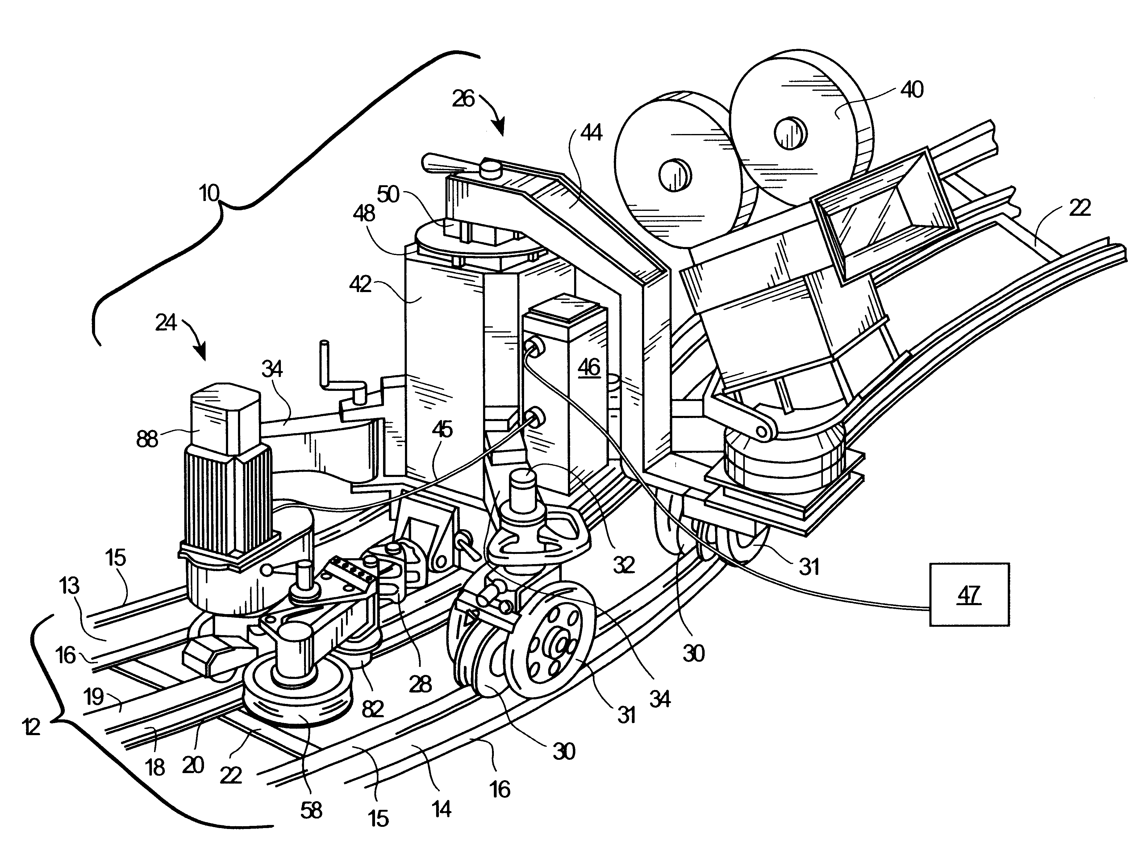
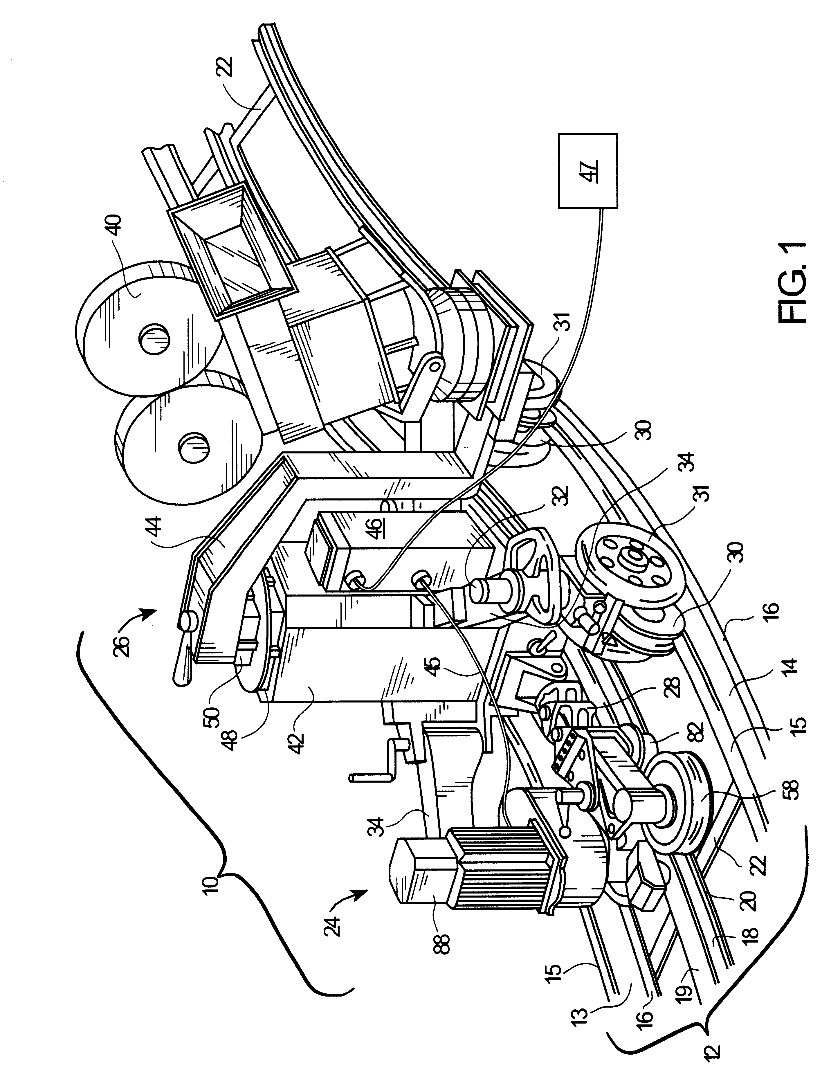
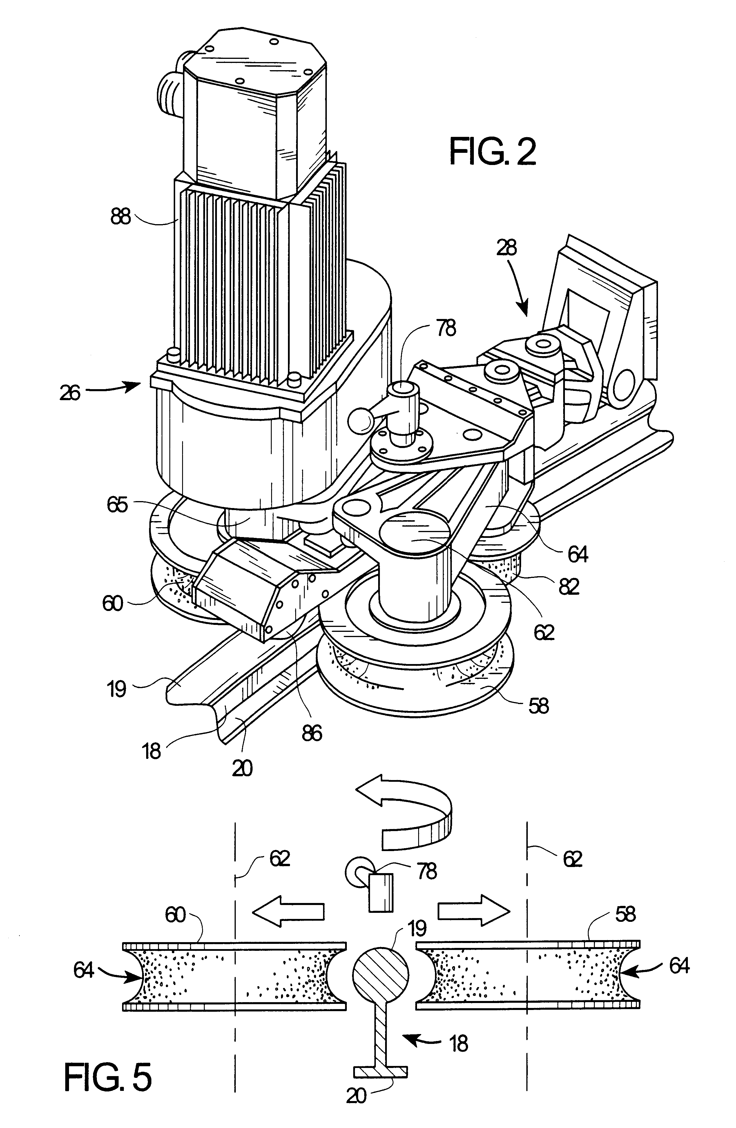
FIG. 1 illustrates the overall configuration of the self-propelled camera dolly 10 in accordance with one embodiment of the present invention. The dolly 10 is designed to operate on a three-rail track system 12. In the specific embodiment illustrated, the outer parallel rails 13 and 14 are about 23 inches apart, each with a 1.375 inches diameter round contact surface 15 for the wheels. The round contact surface 15 is elevated from the base 16 by several inches. The center rail 18 has a 1.5 inch diameter cross-section, with a round contact surface 19 which is elevated from the base 20 (see also FIG. 5). The three rails 13, 14 and 18 are spaced apart by spacing bars ...


PUM


Abstract

A camera positioning system comprising a track having two parallel outer rails and a center rail, a self-propelled camera positioning device comprising a chassis configured to support a camera, wheels coupled to the chassis for riding on the outer rails of the track, and a drive unit for propelling the chassis along the track, said drive means comprising at least one roller coupled to the chassis for engaging the center rail of the track, and a motor for rotating said at least one roller against the center rail, thereby positioning the chassis along the track; and a control logic for controlling the drive unit.

Description

1. Field of the InventionThe present invention relates generally to the field of motion picture production systems, and more particularly, to an improved apparatus for positioning a camera for motion picture photography.2. Description of the Related ArtSpecial effects have played an important role in motion picture productions since the early days of the film industry. In recent years, numerous box office hits testify to the captivating power of special effects, and underscore the significance of special effects in contemporary film making. With each new motion picture production, the film makers are pushing the envelope to out do the last production in special effects. State of the art digital technologies have become a significantly part of special effects. For example, the quality of an image obtained by composite photography may be significantly improved by using digital processes in putting together the image.While modern digital technologies may allow compositing two or more i...

Claims


Application Information

Patent Timeline
IPC IPC(8): B61C13/00F16M11/00F16M11/42F16M11/20F16M11/28
CPCB61C13/00F16M11/28F16M11/42F16M11/425F16M11/10F16M11/18F16M11/2064F16M11/08
Inventor WALTON, BARRYSCHULTZ, BILLCORNELIUS, DAVIDBARKER, CHRIS
Owner SONY CORP
Learn More