Rack lamp

a technology for rack lamps and lampshades, which is applied in the field of rack lamps, can solve the problems of not allowing retroactive mounting or retrofitting of lighting, complex and expensive construction, and difficult implementation, and achieves the effect of simple and inexpensive design, easy, securely and removably fastened

Inactive Publication Date: 2001-08-21
DECOR METALL KARL BECKER
View PDF9 Cites 50 Cited by
  • Summary
  • Abstract
  • Description
  • Claims
  • Application Information

AI Technical Summary

Benefits of technology

It is the object of the present invention to create a lighting fixture with a simple and inexpensive design, which can be easily, securely and removably fastened to the front edge of the shelving levels of the display stand for articles of merchandise and has advantageous illumination areas for the shelf below and towards the front of the display stand in such a way that this lighting does not require any special arrangements at the level of shelving to illuminate same.

Problems solved by technology

For this type of lighting each level of shelving, i.e., each individual shelf panel must, therefore, be specially equipped, which results in a complex and expensive construction and does not permit retroactive mounting or retrofitting of the lighting.
The fastening method in the above design is complex and also not very easy to implement with the shelving used in display stands for articles of merchandise.
Furthermore, no specific illumination of the front and the next lower level of shelving is achieved, instead light is projected onto individual areas.
Furthermore, this known lighting fixture, due to its lack of a profile area, does not permit an advantageous affixing of price indicator labels, etc.

Method used


Image

  • Rack lamp
  • Rack lamp

Examples


Embodiment Construction

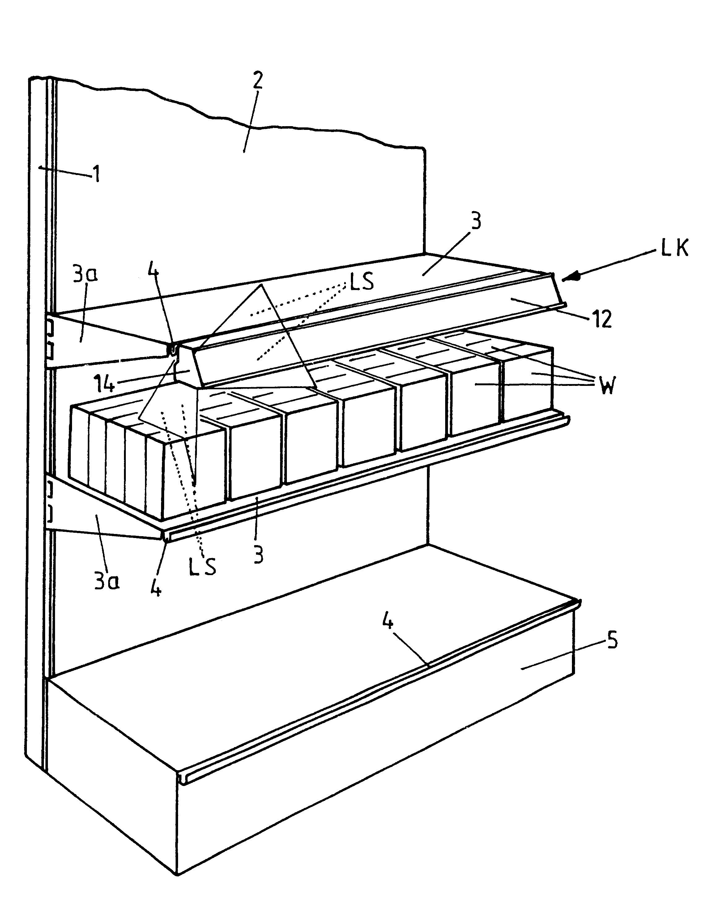
The display stand for articles of merchandise (W) of various kinds incorporates two upright supports (1), one on each side, and between them a back wall (2) and a plurality of tiered levels of shelving hung as display shelves (shelf panels) (3) with side consoles (3a) in slits provided in the supports (1). The display stand may furthermore have a base (5) to be used as a space for placing and storing merchandise (W).

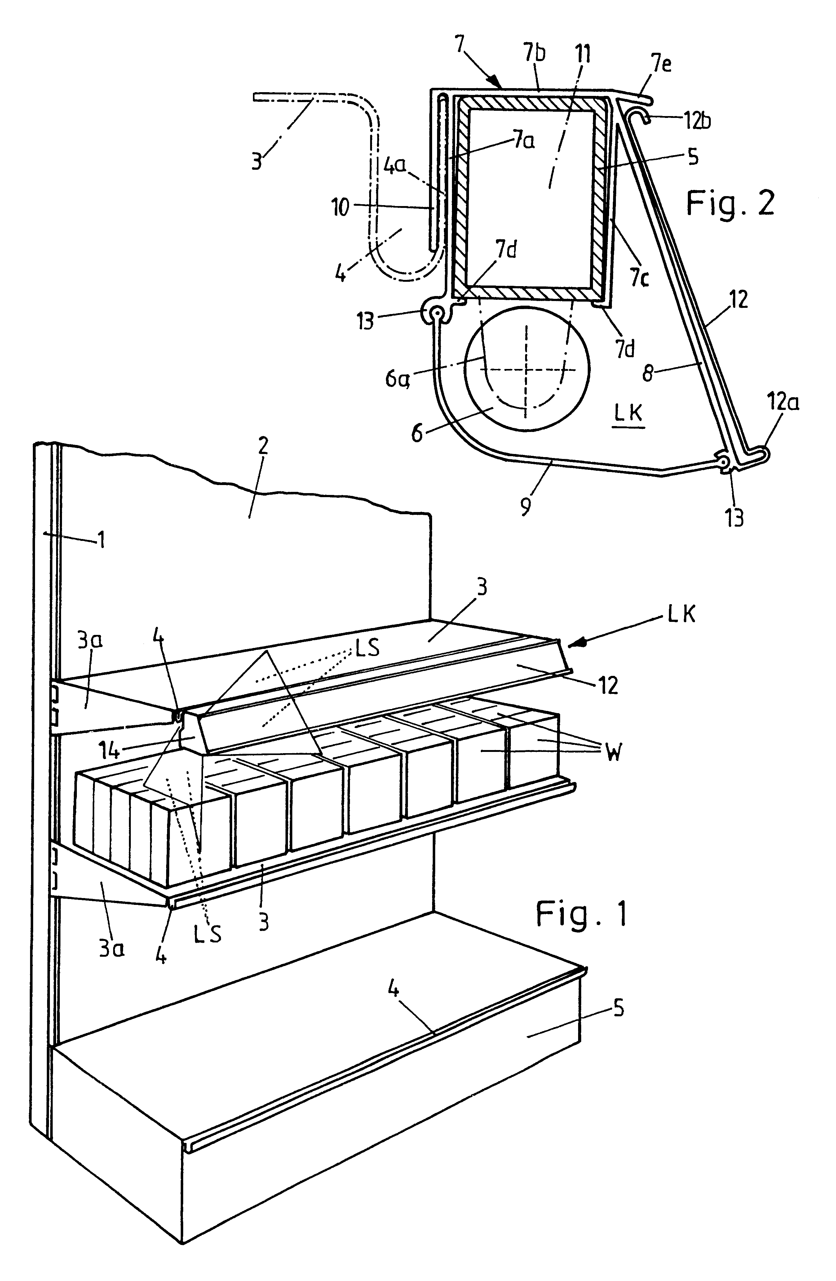
The lighting fixture for / on a display stand for articles of merchandise of this type is provided for each level of shelving (3) and designed in the form of an adaptable lighting fixture to be removably hung at the front edge of the display shelf (3) at the respective level of shelving, projecting light beams (LS) onto the shelf front face and the next lower shelf (3).

The adaptable lighting fixture incorporates a light channel (LK) to be fitted into a U-shaped mold (4) at the front of the display shelf (3) and extending along the entire width of the display shelf and hous...


PUM


Abstract

Disclosed is a lamp for a display stand or a rack, to be secured to a shelf and designed as an adaptable lamp to be removably hung at the shelving edge (3) and to project light beams (LS) on the shelf front face and the lower part of the display rack (3). The inventive adaptable lamp resembles a light channel to be fitted into a U-shaped moulding in the rack front face (3) in such a way that it occupies the whole width of the light channel, in which both the lamp casing and the lamp itself, preferably a set of fluorescent lamps, are incorporated. The light channel (LK) profile (7) is designed so that the channel can house the lamp casing in a fixed position (5), and that the front and lower profile area (8, 9) can let the light beams (LS) through.

Description

1. Technical Field of the InventionThe present invention relates to a lighting fixture for / on a display stand for articles of merchandise to illuminate each level of shelving.2. Prior ArtA lighting fixture for display stands has become known, for example, from DE 295 15 221 U1, in which the display stand lighting fixture is firmly integrated into each level of shelving to illuminate the merchandise placed on the shelves. To achieve this effect, the lateral support arms for the display shelves are extended towards the front, and extended at their ends, at a distance from the front edge of the shelf, by a cross-profile inside which illumination means are housed.For this type of lighting each level of shelving, i.e., each individual shelf panel must, therefore, be specially equipped, which results in a complex and expensive construction and does not permit retroactive mounting or retrofitting of the lighting.From GB-PS 1 136 188 an adaptable lighting fixture has furthermore become know...

Claims


Application Information

Patent Timeline
Patent Type & Authority Patents(United States)
IPC IPC(8): A47F11/00A47F11/10F21V21/02F21S8/00F21S2/00
CPCA47F11/10F21S8/00F21V21/02Y10S362/812F21Y2103/00
Inventor VOSSHENRICH, UDO
Owner DECOR METALL KARL BECKER
Why Eureka
Try Eureka