Extruded stabilizer bar pivot bushing having plastic shear plates and method of making same

Inactive Publication Date: 2001-09-11
FORD GLOBAL TECH LLC
View PDF10 Cites 25 Cited by
  • Summary
  • Abstract
  • Description
  • Claims
  • Application Information

AI Technical Summary

Problems solved by technology

It is believed that injection molding is relatively expensive because it requires injection molding capital equipment and a die that has one or more mold cavities.

Method used


Image

  • Extruded stabilizer bar pivot bushing having plastic shear plates and method of making same
  • Extruded stabilizer bar pivot bushing having plastic shear plates and method of making same

Examples


Embodiment Construction

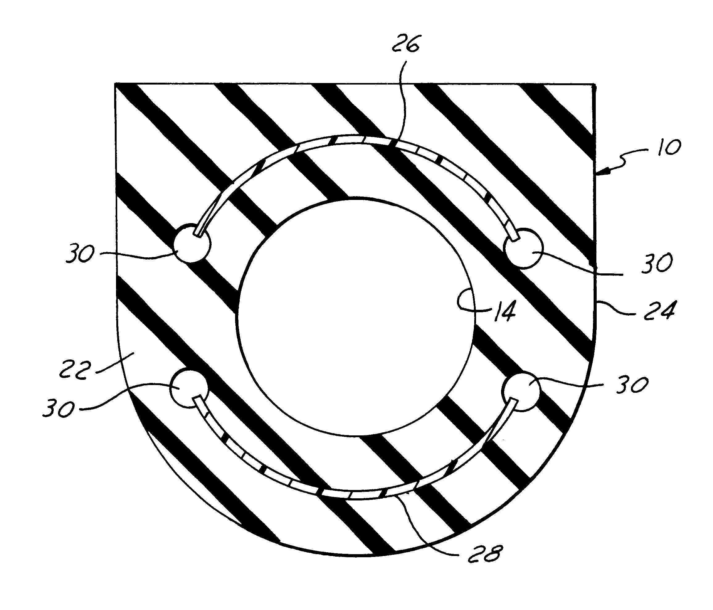
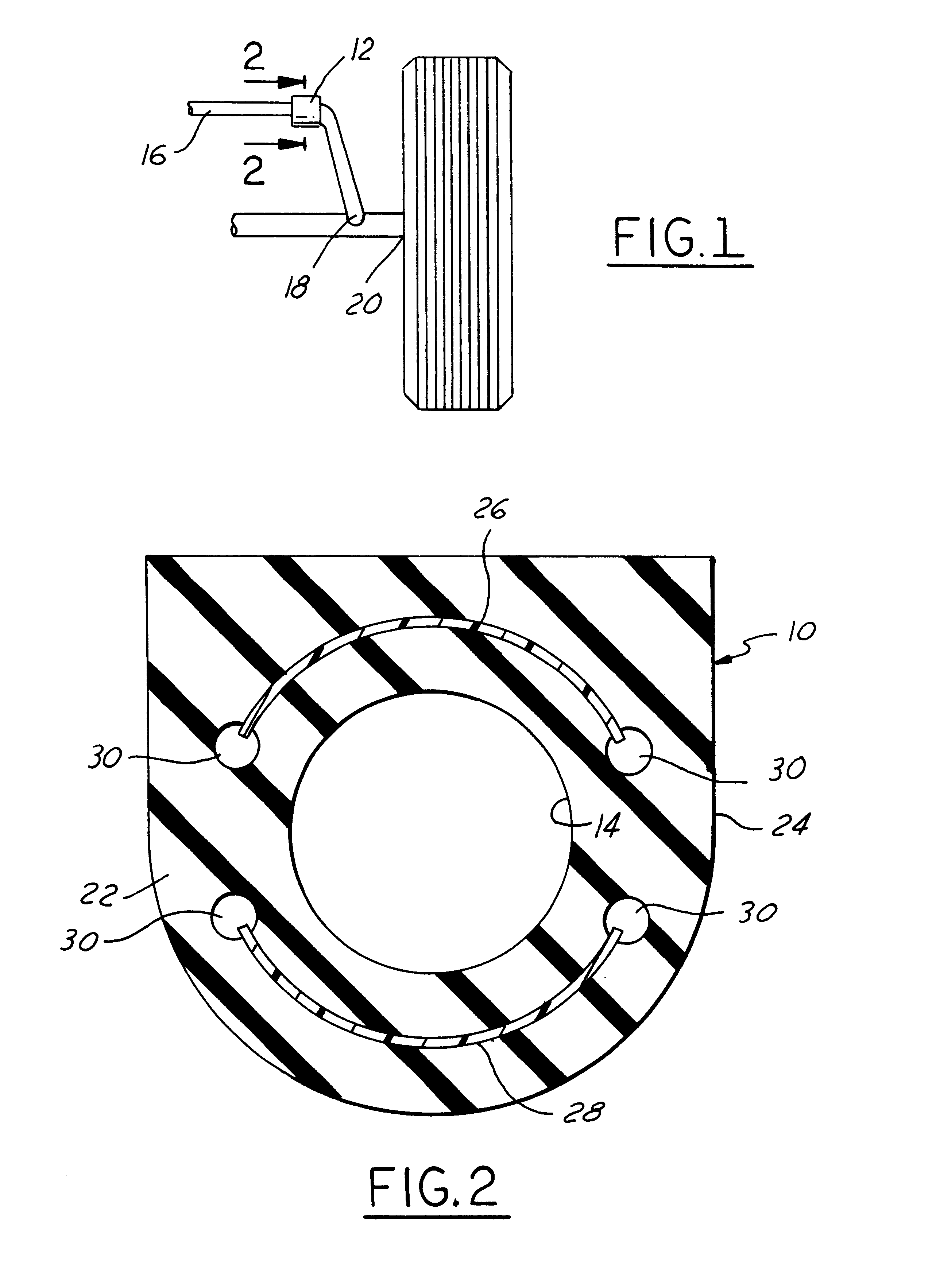
FIGS. 1-2 disclose a stabilizer bar pivot bushing 10 embodying principles of the present invention. Pivot bushing 10 is annular in shape and captured in a metal bracket 12 (see FIG. 1) that is fastened in any suitable manner to a part of the vehicle undercarriage, such as a frame or sub-frame, that is in fixed relation to the vehicle body. Bushing 10 comprises a central through-hole 14 having a shape suitable for fitting to a portion of a stabilizer bar 16. In the example shown, through-hole 14 is circular, defining an inside diameter (I.D.) of the bushing. Stabilizer bar 16 has a shape leading to a free end 18 that is associated in a suitable manner with a portion of the vehicle that is associated with the vehicle undercarriage through a suspension system, in this instance a wheel and axle 20. Stabilizer bar 16 is arranged to resist certain types of motion of the wheel and axle relative to the vehicle undercarriage and body so that the vehicle body will tend to remain more stable d...


PUM

PropertyMeasurementUnit
Lengthaaaaaaaaaa
Diameteraaaaaaaaaa

Abstract

A method of making stabilizer bar pivot bushings (10). At least one length of a substantially plastic material (26, 28) that in transverse cross section has a shape that is arcuate about a central axis passes lengthwise through an extrusion die where an annular elastomeric body (22) is extruded onto the plastic. Then the body is transversely cut, including cutting through the plastic, at locations along the length of the extrusion, thereby creating individual bushings in which the plastic forms at least one shear plate.

Description

1. Field of the InventionThis invention relates to a pivot for a stabilizer bar in a suspension system of an automotive vehicle and a method of making a bushing used in the pivot.2. Background InformationA purpose of a stabilizer bar in a suspension system of an automotive vehicle is to resist rolling of the vehicle body in relation to wheels of the vehicle when the vehicle is making a maneuver such as a turn. A known device for mounting a stabilizer bar with respect to a vehicle body is an elastomeric pivot bushing. The bushing is annular in shape and captured in a metal bracket that is fastened to a part of the vehicle undercarriage that is in fixed relation to the body. Such a part may be a frame or sub-frame of the vehicle for example. A free end of the stabilizer bar is associated in a suitable manner with a portion of the vehicle that is associated with the vehicle undercarriage through a suspension system. The stabilizer bar is arranged to resist certain types of relative mot...

Claims


Application Information

Patent Timeline
IPC IPC(8): B60G21/055B60G21/00F16F1/371F16F1/36
CPCB60G21/0551F16F1/371B60G2204/1222B60G2204/41F16F2226/00B60G2206/8105B60G2204/41043
Inventor SCHAFFER, DAVID HOWARD
Owner FORD GLOBAL TECH LLC
Why Eureka
Try Eureka