
Venetian blind printing system

a venetian blind and printing system technology, applied in printing, typewriters, etc., can solve the problems of damage or distorting the overall image, narrow, curved surface of venetian blinds, and still substantial challenges for engineers

Inactive Publication Date: 2001-09-11
RIDGWAY PAUL ANTHONY
View PDF12 Cites 53 Cited by
  • Summary
  • Abstract
  • Description
  • Claims
  • Application Information

AI Technical Summary

Problems solved by technology

Engineers still encounter some substantial challenges, however, when seeking to print upon certain types of surfaces.
One difficult surface is the narrow, curved surface of a Venetian blind slat.
Although this approach is desirable for its ease of printing, the bending of the Venetian blind slats may damage or distort the overall image.
For example, bending the slat may crack the slat or the printing material thereon.
As with the previous approach, this process may also cause some distortion to the image, since its flat printing does not account for the ultimately curved shape of the image.
Additionally, this approach may also be costly because sufficient adhesive paper is required to completely cover the Venetian blind slats, or else risk an unsightly division between the adhesive paper and the uncovered regions of the slats.
Even with adhesive paper that matches the color of the Venetian blinds, the two materials may ultimately take on different appearances due to diverging wear, dust resistance, dirt accumulation, etc.
Nonetheless, problems have been encountered with silk screening, too.
As a result, the ink does not flow evenly over the curved surface of the slats, and may even run.
Moreover, this procedure is time consuming and expensive because it requires a different individual screen for each slat.
Another problem with silk screening is that an entirely new set of screens must be created to lay down an image on Venetian blinds with different dimensions.
Consequently, known techniques for printing upon Venetian blinds with curved slats are not completely adequate for some applications due to certain unsolved problems.

Method used


Image

  • Venetian blind printing system
  • Venetian blind printing system
  • Venetian blind printing system

Examples


Embodiment Construction

While the foregoing disclosure shows a number of illustrative embodiments of the invention, it will be apparent to those skilled in the art that various changes and modifications can be made herein without departing from the scope of the invention as defined by the appended claims. Furthermore, although elements of the invention may be described or claimed in the singular, the plural is contemplated unless limitation to the singular is explicitly stated.


PUM


Abstract

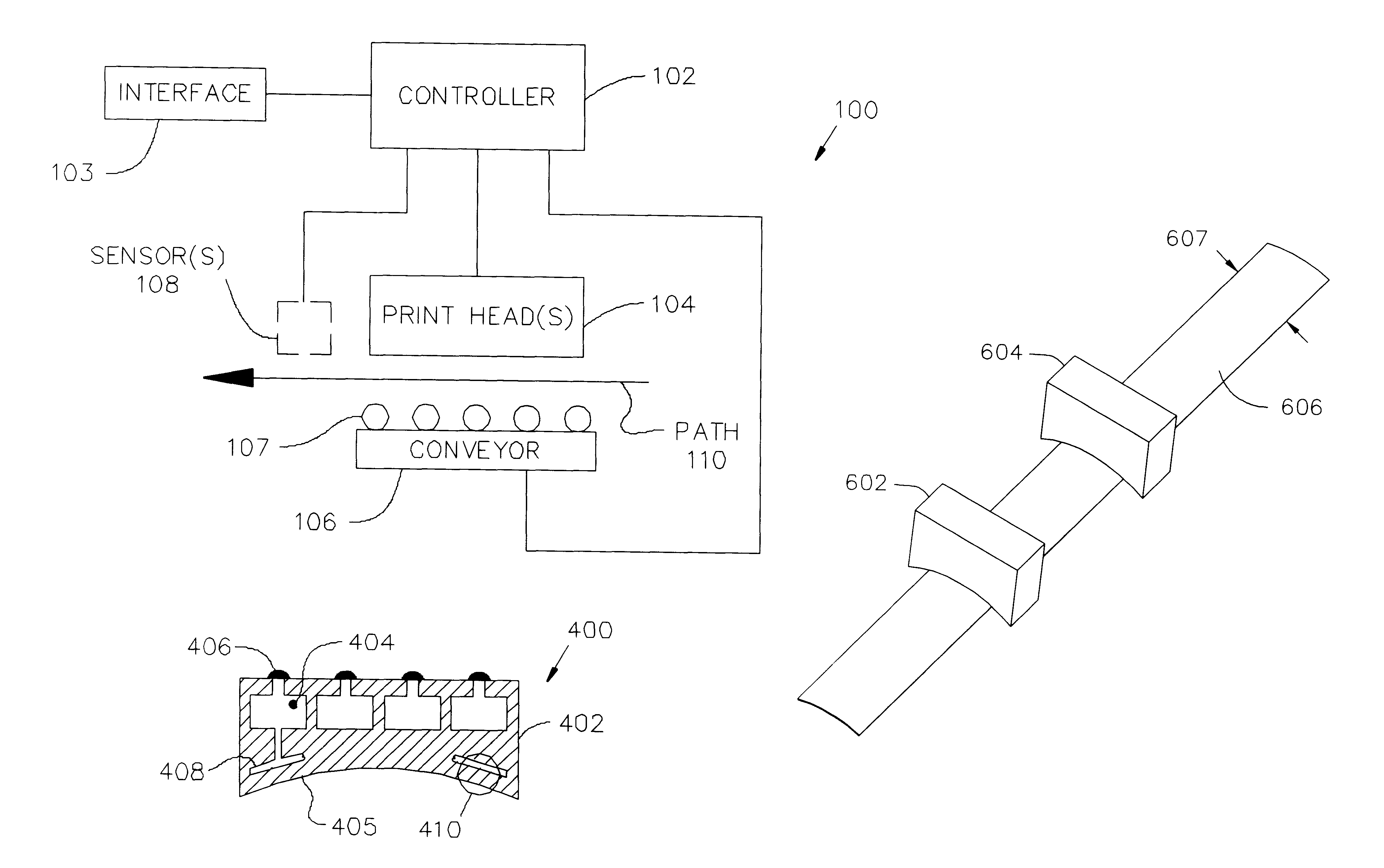
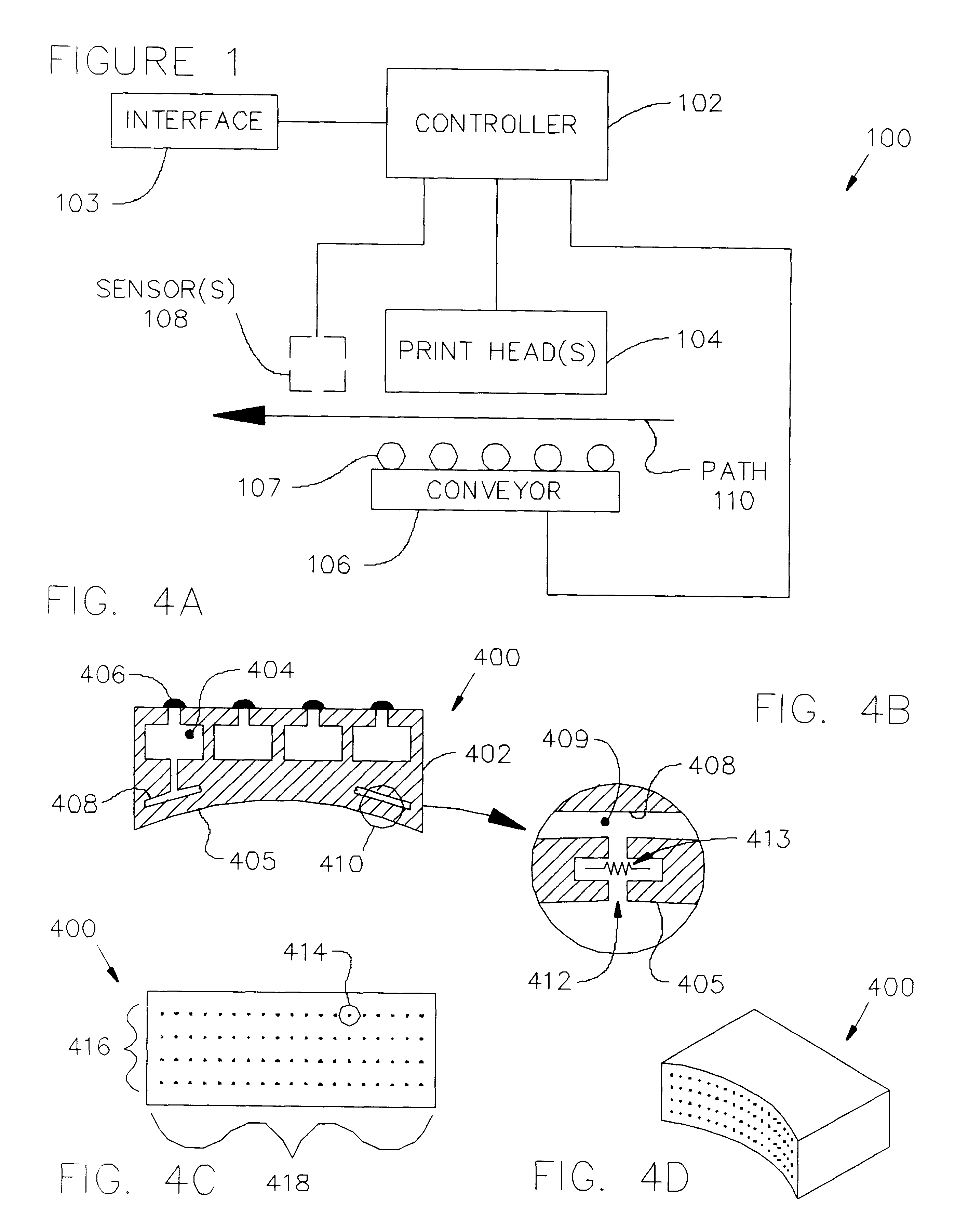
Print heads with arcuate printing surfaces are used to apply images to elongated, laterally curved slats prior to their assembly into Venetian blinds. Each print head includes a print head casing having a concave or convex printing surface forming an arc shape. The print heads are distributed in series along a slat path, which is defined by a conveyor. One or more ink wells are coupled to the print head casing; each ink well may contain a separate color of ink. Many print jet orifices are evenly distributed along the printing surface, and may be arranged in an array with multiple rows and columns, for example. Each print jet orifice is coupled to one of the ink wells by a supply path. During the printing process, slats are longitudinally advanced along the slat path past the print heads. A controller regulates the slat's position relative to the print heads, and controls the position using the conveyor. At selected times, depending upon the slat's position, the controller activates selected ink jets of selected print heads to eject ink upon the curved slat, and thereby imprint a desired image upon the slat. The images imprinted on individual slats are coordinated to provide a desired, overall image spanning the Venetian blinds.

Description

1. Field of the InventionThe present invention relates to the field of printing, and more particularly to the use of curved multi-jet print heads to print upon laterally curved slats prior to their assembly into louvred structures such as Venetian blinds.2. Description of the Related ArtFrom typewriters to laser operated graphics printers, the printing field is ripe with printing devices. Despite the tremendous breadth of potential surfaces to be printed upon, engineers have designed a correspondingly broad selection of printers for many of these jobs. In addition to the usual paper jobs, equipment for printing, engraving, stamping, and the like has been developed for vinyl signs, CD-ROMs, plastics, metals, and many other materials. Airplane skywriting fills an unusual need to place text in the sky, further attesting to mankind's ingenuity in printing just about anywhere.Engineers still encounter some substantial challenges, however, when seeking to print upon certain types of surfa...

Claims


Application Information

Patent Timeline
IPC IPC(8): B41J3/407
CPCB41J3/4073
Inventor RIDGWAY, PAUL ANTHONY
Owner RIDGWAY PAUL ANTHONY
Learn More