Rear projection screen with uniformity of luminance

a technology of luminance and rear projection screen, applied in the field of rear projection screen, can solve the problems of affecting the focal length affecting the appearance of the screen, and affecting the effect of the rear projection screen,

Inactive Publication Date: 2001-09-18
DAI NIPPON PRINTING CO LTD
View PDF13 Cites 35 Cited by
  • Summary
  • Abstract
  • Description
  • Claims
  • Application Information

AI Technical Summary

Problems solved by technology

In the conventional rear projection screens, the diffusion angle is uniform over the entire screen surface, so that there is such a problem that the phenomenon of shading, which will be described hereinafter, tends to occur.
When this color shading is taken into ...

Method used


Image

  • Rear projection screen with uniformity of luminance
  • Rear projection screen with uniformity of luminance
  • Rear projection screen with uniformity of luminance

Examples


example 1

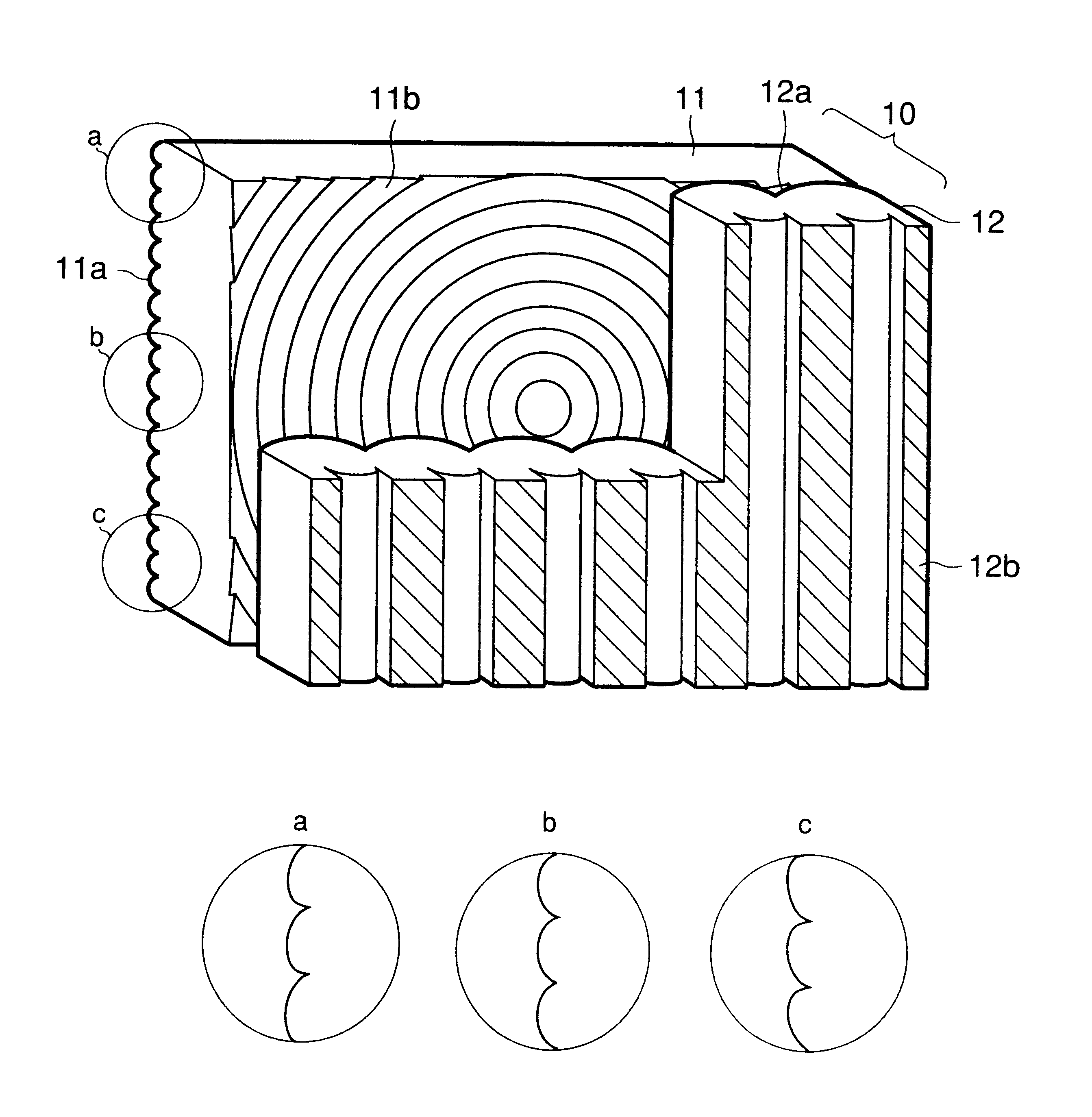
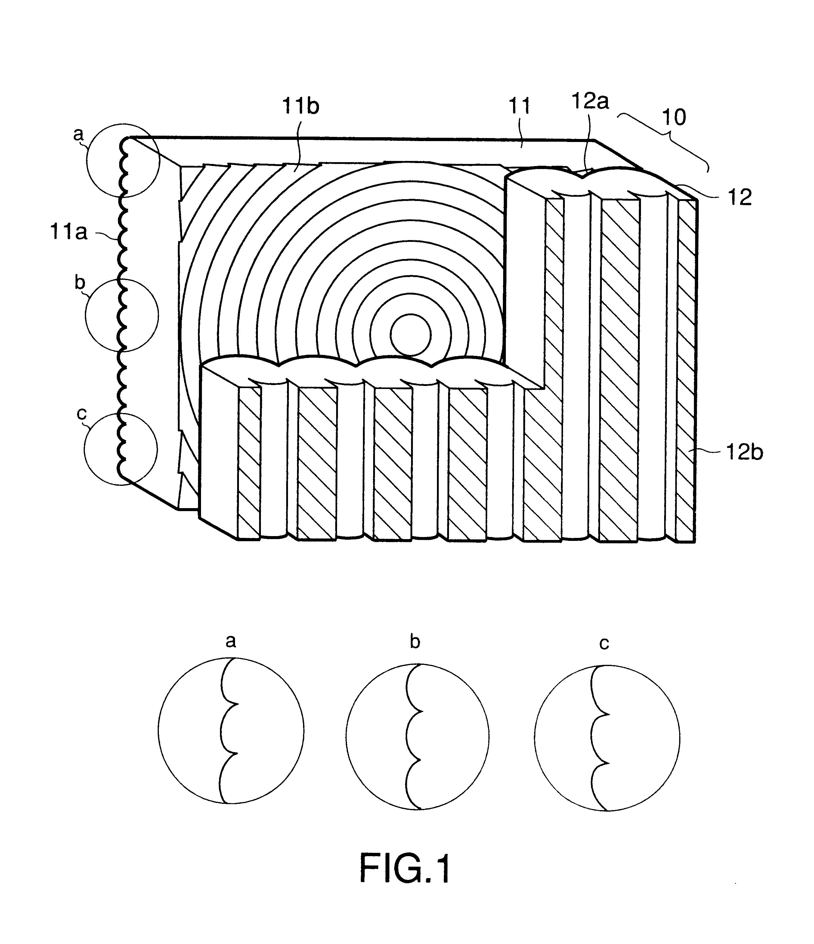
In this example, a rear projection screen 10 as shown in FIG. 1 was produced as a rear projection screen for a 60 inch rear projection type television. In a Fresnel lens sheet 11 for use in this rear projection screen, a lenticular lens 11a for vertical diffusion is formed on the light-entering side of the screen, and a circular Fresnel lens 11b is formed on the light-emerging side of the screen.

Regarding a metal mold used for making the lenticular lens 11a for vertical diffusion, a cylindrical metal mold 32 which would be a master for the lenticular lens 11a for vertical diffusion was produced by the use of a cutting tool 31 whose cross section was in such a shape that three circular arcs were smoothly connected. Specifically, as shown in FIG. 3, by feeding with a constant pitch the cutting tool 31 in the direction indicated by the arrow F along a cylindrical object to be cut, with the object to be cut being rotated in the direction indicated by the arrow R, and by cutting the obje...

example 2

The rear projection screen of Example 2 is essentially identical to that of Example 1 except that the tops of the convex lenses arranged at the upper edge and lower edge, which are in the marginal part of the screen surface, are deviated from the center of the respective convex lenses toward the edge side on the screen surface; and so that the directions of diffusion at the upper edge and lower edge are to be inclined to the edge side on the screen surface.

In this example, since the direction of deviation of the tops of the convex lenses is opposite to that of Example 1 while the shapes of the convex lenses are identical to those of Example 1, the diffusion properties obtainable at the upper edge, central part and lower edge of the lenticular lens for vertical diffusion, respectively correspond to FIGS. 9, 8, and 7, in reverse order to the case of Example 1.

When the rear projection screen 10 of this example is observed from the front (measurement point p1), as can be understood from...


PUM


Abstract

A rear projection screen including a Fresnel lens sheet arranged on the projection side, and a lenticular lens sheet arranged on the observation side. The Fresnel lens sheet has a lenticular lens for vertical diffusion on its light-entering side. The lenticular lens for vertical diffusion containing a plurality of convex lenses that extend horizontally, and these plural convex lenses are arranged with a constant pitch. Further, the diffusion angle of the lenticular lens for vertical diffusion continuously increases, and, at the same time, the direction of diffusion is gradually inclined to the central part as the distance from the central part toward each of the edges on the screen surface increases. The diffusion properties (the angle and direction of diffusion) of the lenticular lens thus continuously vary between the central part and the edges of the screen surface.

Description

1. Field of the InventionThe present invention relates to a rear projection screen comprising a Fresnel lens and a lenticular lens.2. Related ArtRear projection screens that comprise Fresnel lenses for refracting rays projected from an imaging source to make them almost parallel with each other, and lenticular lenses for scattering projected rays to form an image have conventionally been known as screens useful for rear projection type TVs and the like.Further, among the conventional rear projection screens, there has been known a screen in which projected rays are diffused in the horizontal direction by a lenticular lens sheet for horizontal diffusion, and in the vertical direction by both a diffuser and a lenticular lens sheet for vertical diffusion. It is noted that the diffusion angles of these lenticular lens sheets are generally uniform over the entire screen surface.In the conventional rear projection screens, the diffusion angle is uniform over the entire screen surface, so ...

Claims


Application Information

Patent Timeline
IPC IPC(8): G03B21/62G03B21/625H04N5/74
CPCG03B21/625H04N5/74
Inventor TAKAHASHI, YOSHIKIGOTO, MASAHIROWATANABE, HITOMUHONDA, MAKOTOODA, KUMPEITAKAHASHI, KATSUNORI
Owner DAI NIPPON PRINTING CO LTD
Why Eureka
Try Eureka