Ink refillable stamp

Inactive Publication Date: 2001-10-16
SHIH SHINY
View PDF6 Cites 70 Cited by
  • Summary
  • Abstract
  • Description
  • Claims
  • Application Information

AI Technical Summary

Problems solved by technology

Thus, patterns of the conventional stamp also cannot be formed with other configuration except the rectangle.
If it is possible to make other patterns such as a circle, a triangle, or a polygon on the rectangular stamping body, it is not easy for a user to position the stamp in a correct location because of the difference between the pattern and the stamping body.

Method used


Image

  • Ink refillable stamp
  • Ink refillable stamp
  • Ink refillable stamp

Examples


Embodiment Construction

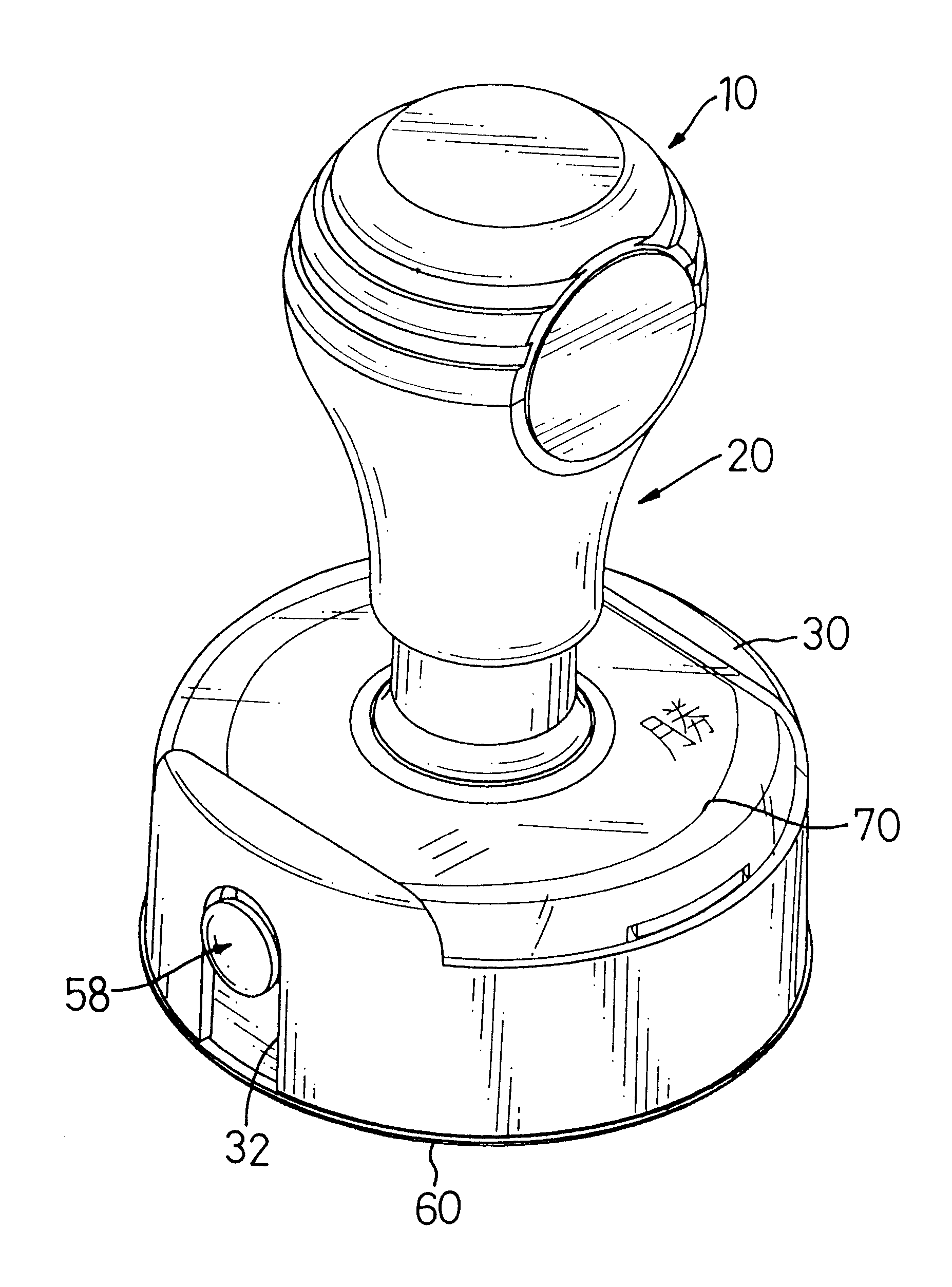
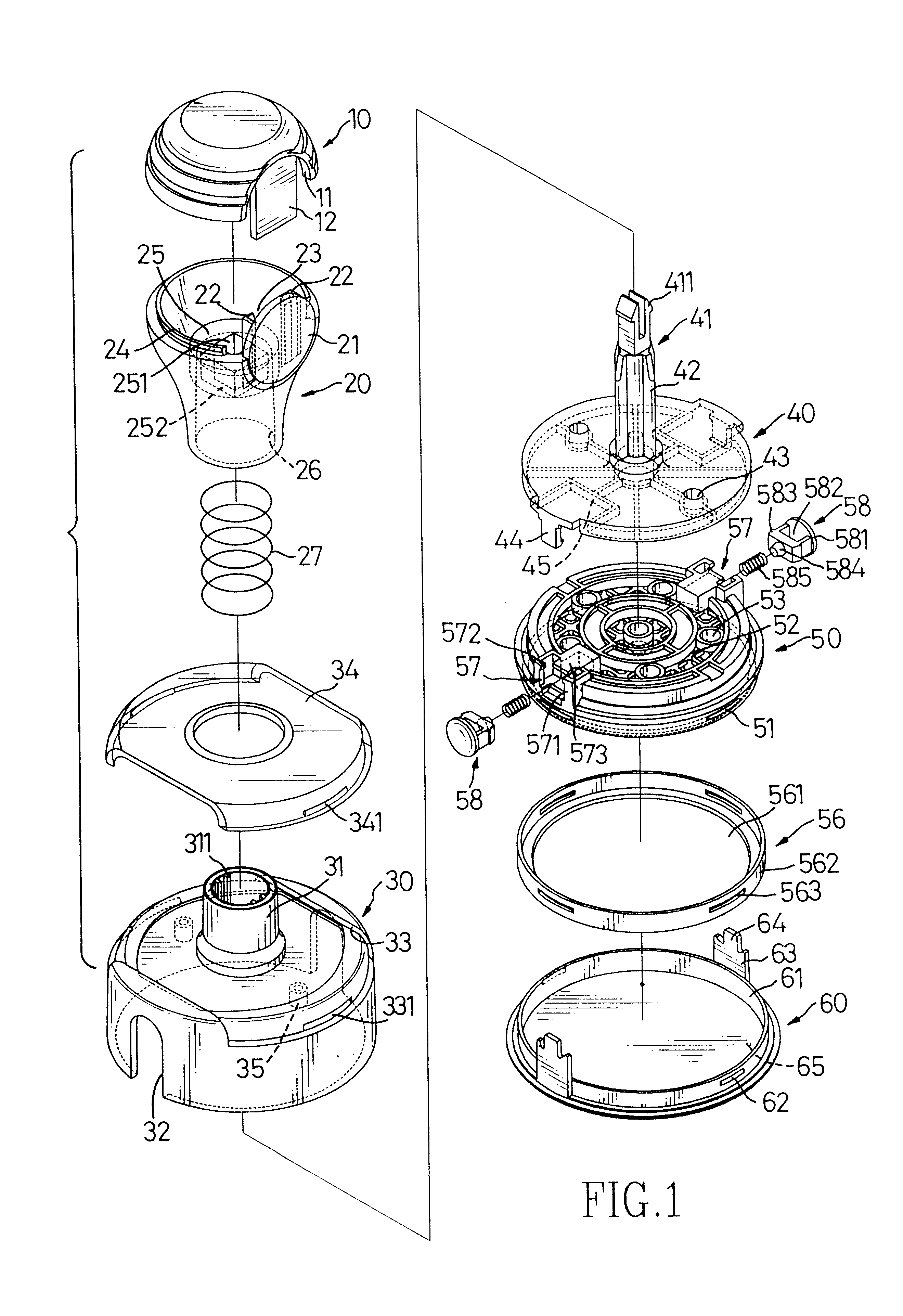
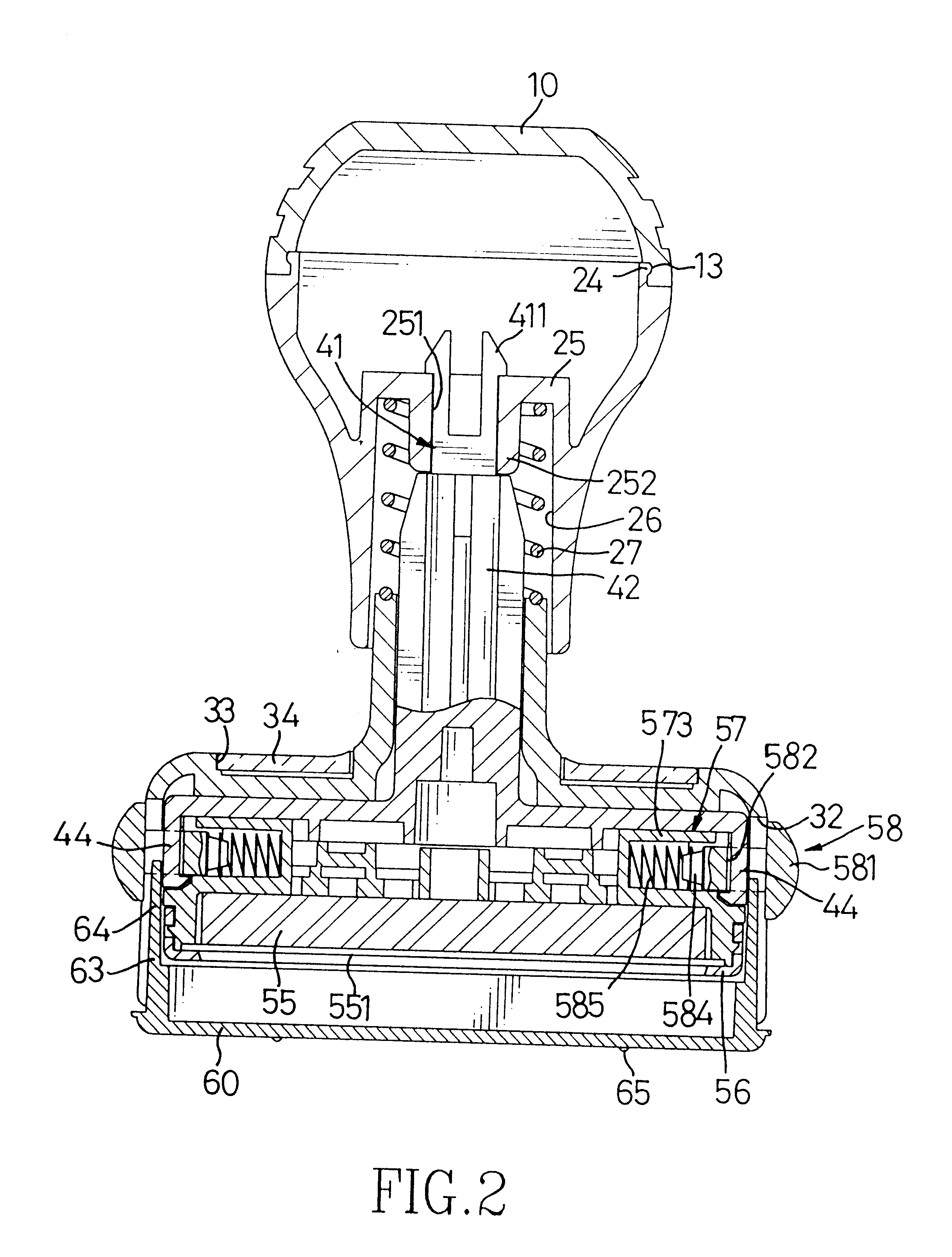
Referring to FIGS. 1 and 2, an ink refillable stamp in accordance with the present invention is composed of a cap (10), a handle (20), a housing (30), an upper seat (40), a lower seat (50) and a bottom cover (60).

The cap (10) has a first notch (11) defined at a periphery thereof and a tab (12) formed in the notch (11) and extending downwards. A circular groove (13) is defined at a bottom of the cap (10).

The handle (20) has a cutout (21) vertically defined in an outer periphery thereof Two first ears (22) defining a channel (23) therebetween are formed on an upper edge of the cutout (21). The tab (12) extends through the channel (23) and urges against the cutout (21). A first ring (24) is formed on an upper surface of the handle (20) and received in the groove (13) of the cap (10). The handle (20) further has a passage (26) longitudinally defined therethrough and a flange (25) formed at an inside end of the passage (26). The flange (25) has a square orifice (251) defined through a sq...


PUM


Abstract

An ink refillable stamp has a cap (10), and a handle (20) mounted under the cap (10). The handle (20) has a passage (26) defined therein and a first resilient member (27) is received in the passage (26). A housing (30) has a tubular portion (31) formed on a top surface thereof and received in the passage (26). An upper seat (40) is received in the housing (30) and has a pole (41) formed on a top surface thereof and extending through the tubular portion (31) and the passage (26) and engaged in the handle (20). A lower seat (50) is detachably mounted beneath the upper seat (40) and has a plurality ink inlets (53) defined through a top surface thereof A chamber (54) is defined at a bottom portion of the lower seat (50) and in communication with the ink inlets (53). A sponge (55) is received in the chamber (54) and a stamping sheet (551) is provided under the sponge (55). A bottom cover (60) is provided on the lower seat (50).

Description

1. Field of the InventionThe present invention is related to an ink refillable stamp, and more particularly to an ink refillable stamp which can be formed with any configurations of stamping sheet such as circular, rectangular, triangular and is refilled with ink easily.2. Description of Related ArtReferring to FIGS. 8 and 9, a conventional ink refillable stamp has a handle (81) with a cap (80) mounted on a tubular portion of an outer housing (82). An inner housing (83) is received in the outer housing (82) and has a stamping body (84) mounted therein by an upper frame (841) and a lower frame (842). The stamping body (84) has a plurality of ink inlets (843) defined in an upper surface thereof and each ink inlet (843) has one of a plurality of pins (844) formed therein. A sponge (86) is provided in the stamping body (84) and a stamping sheet (87) is provided beneath the sponge (86). A bottom cover (85) is provided under the stamping body (84). The outer housing (82), the inner housin...

Claims


Application Information

Patent Timeline
IPC IPC(8): B41K1/52B41K1/00
CPCB41K1/52
Inventor SHIH, SHINY
Owner SHIH SHINY
Why Eureka
Try Eureka