Cosmetic case

a cosmetic case and body technology, applied in the field of cosmetic case assembly, can solve the problems of cosmetic material quality degradation, and clumsy and inconvenient handling,

Inactive Publication Date: 2001-11-06
YOSHIDA KOGYO KK
View PDF28 Cites 49 Cited by
  • Summary
  • Abstract
  • Description
  • Claims
  • Application Information

AI Technical Summary

Problems solved by technology

The use of a hinged cover refill case, however, demands that the user open the outer case cover and refill case cover in multiple sequential operations that are, in many cases, clumsy and inconvenient.
Even if a cosmetic case provides an efficient sealing effect for the substance contained therein, the condensation of solvents contained within the sealed cosmetic material can result in condensate droplets collecting on the surface of the cosmetic material and degrading the quality of said material.
As the aforesaid Japanese unexamined patent publication No.8-347 calls for a separate inner tray and cover to which separate elastic packing pieces must be installed, the number of components comprising the cosmetic case increases, the structure becomes more complicated, and the assembly operation for the cosmetic case becomes more expensive and time consuming.
Moreover, the cosmetic case is relatively inconvenient to use as the outer and inner covers require separate operations to open and close.
As the aforesaid Japanese unexamined patent publication No.9-98829 requires a first joint at the separator and case wall, and a second joint at the inner tray, a relatively complex structure is required which correspondingly makes the fabrication of tooling, which is required to manufacture the case, more complex and expensive.
Resultantly, there is no significantly improvement in the ease with which the covers can be opened.

Method used


Image

  • Cosmetic case
  • Cosmetic case
  • Cosmetic case

Examples


first embodiment

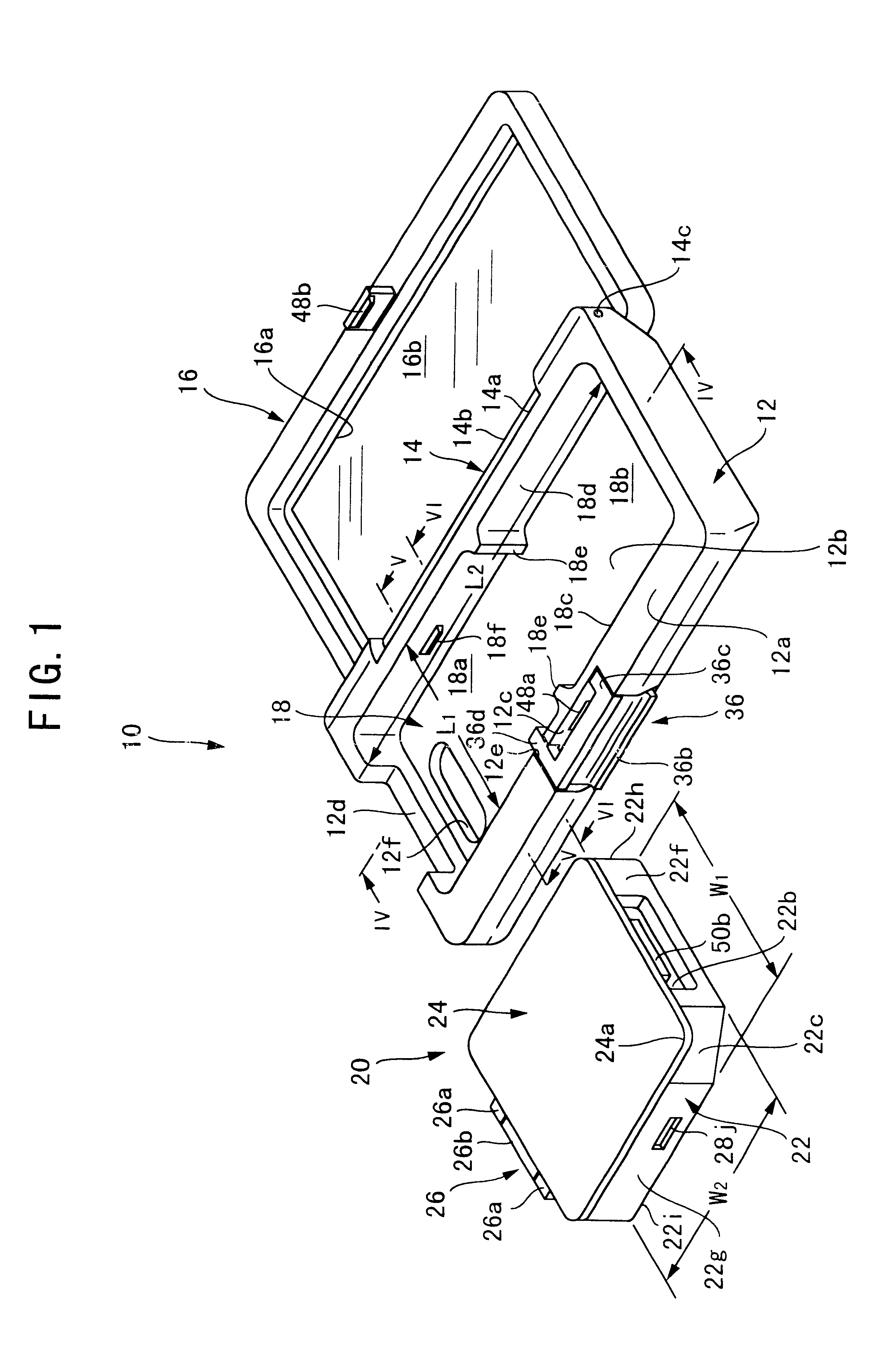
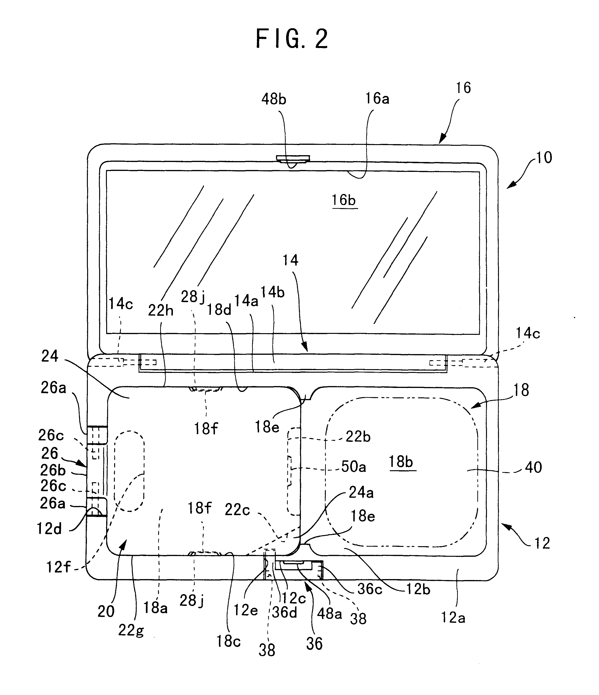
This first embodiment of the cosmetic case invention has presented a structure in which a single pushing action applied to a push-piece is able open both outer cover 16 and inner cover 24 of the refill-type cosmetic case. The aforesaid structure not only provides means for convenient opening of a dual-compartment refill-type cosmetic case, but also provides for the efficient use of the inner case area as a result of the minimum amount of space required by the pivoting action of the aforesaid push-piece.

As cutout section 12d is provided on outer wall 12b as clearance for hinge mechanism 26, the opening of inner cover 24 does not interfere with outer wall 12b, thereby allowing inner cover 24 to open completely in an outward direction from outer case 12 as means of providing free and convenient access to the cosmetic material. As further shown in FIG. 7, the mechanism can be structured so inner cover 24 pushes up against outer cover 16 when push-piece 36 is pressed, thus creating a lar...

case 20

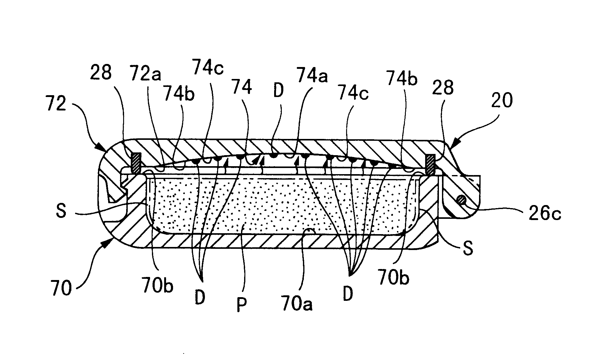
Refill case 20 is secured within first compartment 18a of inner space 18 by means of ribs 18e, and by further means of tabs 18f of inner walls 18c and 18d inserting into slots 22j on inner case 22. Cosmetic application puff 40 or other like device can be held in second compartment 18b.

Refill case 20 is indexed within inner space 18 by means of the slight protrusion of ribs 18e formed on inner walls 18c and 18d. As a result of this structure, the need for a separator wall to define first compartment 18a (for refill case 20) and second compartment 18b (for the aforesaid application puff 40) is eliminated. As ribs 18e only protrude a small amount within inner space 18, inner space 18 can be generally defined as one continuous space over the length of outer case 12, a characteristic which simplifies the formation of inner space 18 through the use of less complex dies to manufacture outer case 12. While the figures show ribs 18e formed on both wall 18c and 18d, a single rib 18e may be fo...

case 12

outer case 12,

outer cover 16 open and closably installed to outer case 12,

inner case 22 of refill case 20, inner case 22 being installable or removable to first compartment 52b inner tray 52,

inner cover 24 open and closably attached to inner case 22,

main latch mechanism 48 installed between outer cover 16 and outer case 12 and forming an open and closable joint between outer cover 16 and outer case 12

sub-latch mechanism 50 installed between inner case 22 and inner cover 24 and forming an open and closable joint between inner case 22 and inner cover 24,

push-piece 58 installed to outer case 12 and capable of operating in a manner as to release main latch mechanism 48,

and flex piece 60 formed as an integral component extending inwardly from outer case 12, residing between outer case 12 and inner cover 24, and capable of releasing main latch 50 through a displaced movement provided by push-piece 58.

Push-piece 58 is structured as a hollow body square in cross section, and installed in cu...


PUM


Abstract

A cosmetic case containing a replaceable inner case which can be easily removed or inserted, and which is specifically structured to maintain the cosmetic material contained therein in a fresh and useable condition. The invention is comprised of an outer case with a floor area and inner peripheral wall defining a space for an inner container, an outer cover attached by a hinge to the outer case, a main latch employed to hold the outer cover closed, a replaceable inner container providing a cosmetic holding space, an inner container cover capable of opening or closing over the cosmetic holding space, and a sub-latch employed to hold the inner cover closed against the inner container. The inner case is equipped with a hinge part to allow opening and closing of the inner cover, the hinge part fitting into a cutout section on the peripheral wall of the outer case so as to expose the hinge and thus allow wide angle opening of the inner case cover. Inner case installation is aided by small protruding ribs formed within the outer case with the purpose of indexing and securing the inner case. An orifice is provided in the floor of the main case to allow the inner case to be pushed up and removed by finger pressure applied from below. The cosmetic case is characterized by a push-type latch mechanism which opens the outer and inner case covers simultaneously in one movement, an effective sealing mechanism between the inner case and cover, and specific inner cover structures to inhibit the fall of condensation droplets onto the cosmetic surface.

Description

1. Field of the InventionThe invention relates to a cosmetic case assembly of the type in which a sub-case can be easily installed to or detached from a main case, and in which each of the aforesaid cases is equipped with a cover which can be easily opened and closed as a means of allowing convenient access to the cosmetic material contained therein, and as further means of preserving the contained cosmetic material in a desirable and usable condition.2. Description of the Related ArtCosmetic cases are generally employed as convenient portable containers for carrying personal-use cosmetic substances. These cases consist of a container body in which a cosmetic substance is held, and an openable cover installed to the case as means of allowing access to the cosmetic material as well as means of sealing the internal case area when the cosmetic material contained therein is not being used. A latch mechanism is employed to keep the cover closed, and can be activated to open the cover whe...

Claims


Application Information

Patent Timeline
Patent Type & Authority Patents(United States)
IPC IPC(8): A45D33/00A45D33/26A45C13/00A45C13/10A45D33/24A45D40/22
CPCA45C13/008A45C13/1084A45D33/006A45D33/24A45D40/22
Inventor YUHARA, YUKITOMOMIYOKAWA, KIYOKAZUKUMAGAI, MICHIAKISUGIYAMA, TAKASHI
Owner YOSHIDA KOGYO KK
Why Eureka
Try Eureka