
Boot binding system

a technology of boot support and binding mechanism, which is applied in the direction of snowboard bindings, skis, skates, etc., can solve the problems of no substantial evidence for the case of skiboard safety release bindings, the need for boot support to be attached, and the snowboard bindings do not employ a safety release mechanism, etc., to achieve low manufacturing cost, high performance, and ease of us

Inactive Publication Date: 2001-11-13
CARON ALPINE TECH
View PDF12 Cites 38 Cited by
  • Summary
  • Abstract
  • Description
  • Claims
  • Application Information

AI Technical Summary

Problems solved by technology

Such bindings would require the user to willfully attach and detach the boot from the ski before and after use and did not employ any type of safety release mechanism.
Numerous injuries to skiers' legs forced the development of safety release ski bindings.
Snowboard bindings do not employ a safety release mechanism to release the snowboarders boot while in use.
Consequently there is no substantial evidence for the case of employing safety release bindings on skiboards.
Like snowboard bindings, skiboard bindings attach and detach the boot from the skiboard only when the user desires and do not employ a safety release mechanism to release the snowboarders boot while in use.
A disadvantage to an adjustment means comprising a lead screw is that the boot support must be affixed to the binding plate in a manner such that it can slide when the lead screw is turned.
Such a connection inevitably prevents rigid holding of the boot support, allowing the boot support to move when in use.
These movements, especially in the lateral direction, detract from the bindings overall performance because the bindings rigidity is reduced.
First, size adjustment requires removal of the screws, which lends itself to loss of the fastener.
Second, two screws are required to properly prevent the boot support from movement, adding to user complexity and cost.
Additionally, to accommodate the size range, the binding plate has many costly threaded holes, each of which contributes to the manufacturing cost.
Lastly, the size adjustment increment is limited by the required spacing of the tapped holes.
However, a disadvantage of this binding is the cost increase to add the mating teeth to the binding plate and boot support, although this cost does not make the total binding cost unreasonable.
The cost of this implementation is a disadvantage due to the multiplicity of locating holes and the expense associated with the locating pins.
This implementation has the same disadvantage evidenced in most lead screw based bindings, specifically that the part dimensions and tolerances needed for the binding plate and boot support to be slideable prevent rigid holding of the boot support.
This allows the boot support to move when in use and thereby decreasing the bindings performance.
When the lever cam is engaged, the boot support and fasteners are not free to slide along the slots in the binding plate.
A disadvantage to this implementation is the product's complexity and associated cost.
Specifically, two fasteners are required per boot support, thereby requiring two slots in the binding plate, which all contribute to the manufacturing cost.
Additionally, the lever cam and mating teeth in the binding plate contribute to the cost.
This introduces concerns about part wear and durability.
The resilient material also dampens some of the unwanted vibrations that would otherwise be transmitted through the binding to the user.

Method used


Image

  • Boot binding system
  • Boot binding system
  • Boot binding system

Examples


embodiment

Rectangular Platform and Rectangular Bail Block Embodiment

FIGS. 12 and 13 show a rectangular platform 750 having a rectangular platform bottom 752, rectangular platform edges 754a,b, and a rectangular platform top 756. A rectangular bail block 774 has a rectangular bail block top 772 generally in contact with boot 601. A rectangular bail block outer edge 770a,b limits the extent of rectangular bail block 774. A rectangular bail block bottom wall thickness 768a,b is opposite rectangular bail block top 772. Rectangular bail block recessed walls 766a,b approximately face each other. A rectangular bail block recessed bottom 764a,b opposes rectangular platform bottom 752. A rectangular bail block recessed edge 762a,b is adjacent to rectangular platform edges 754a,b. A rectangular bail block recessed inner 760 is opposite rectangular platform top 756. As shown in FIG. 13, rectangular platform 750 and rectangular bail block 774 are sized such that a rectangular lock down gap 776 exists whe...


PUM


Abstract

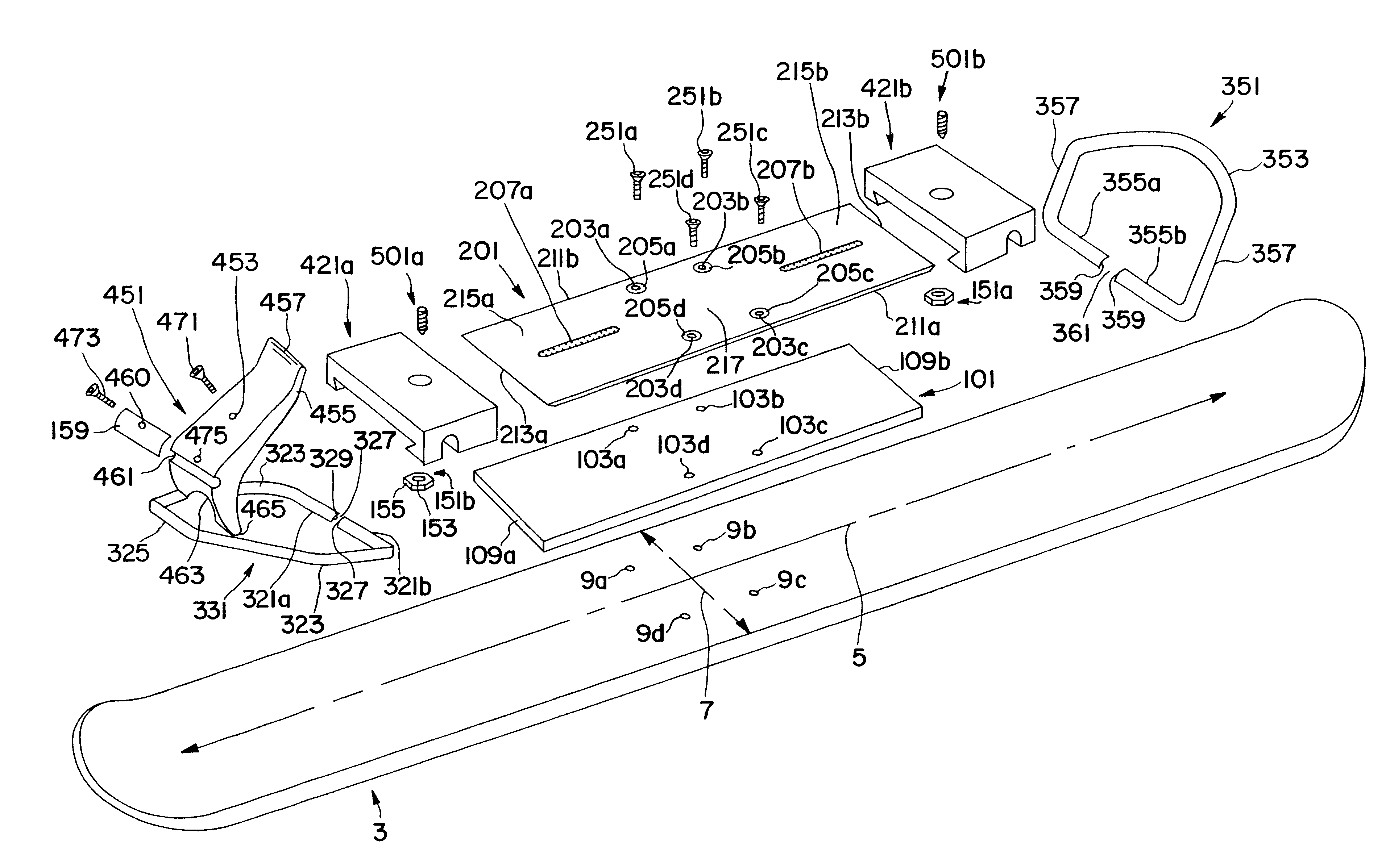
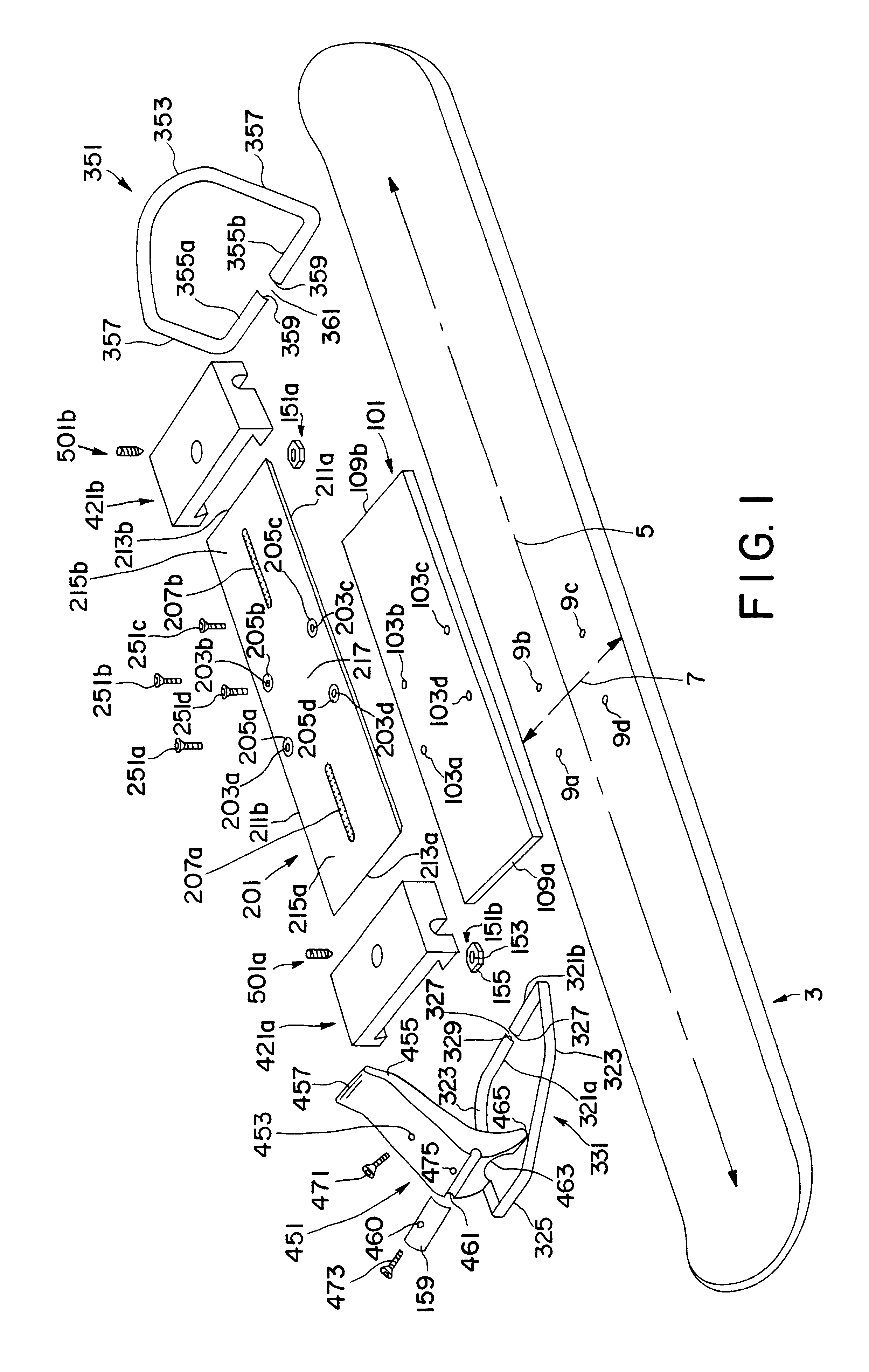
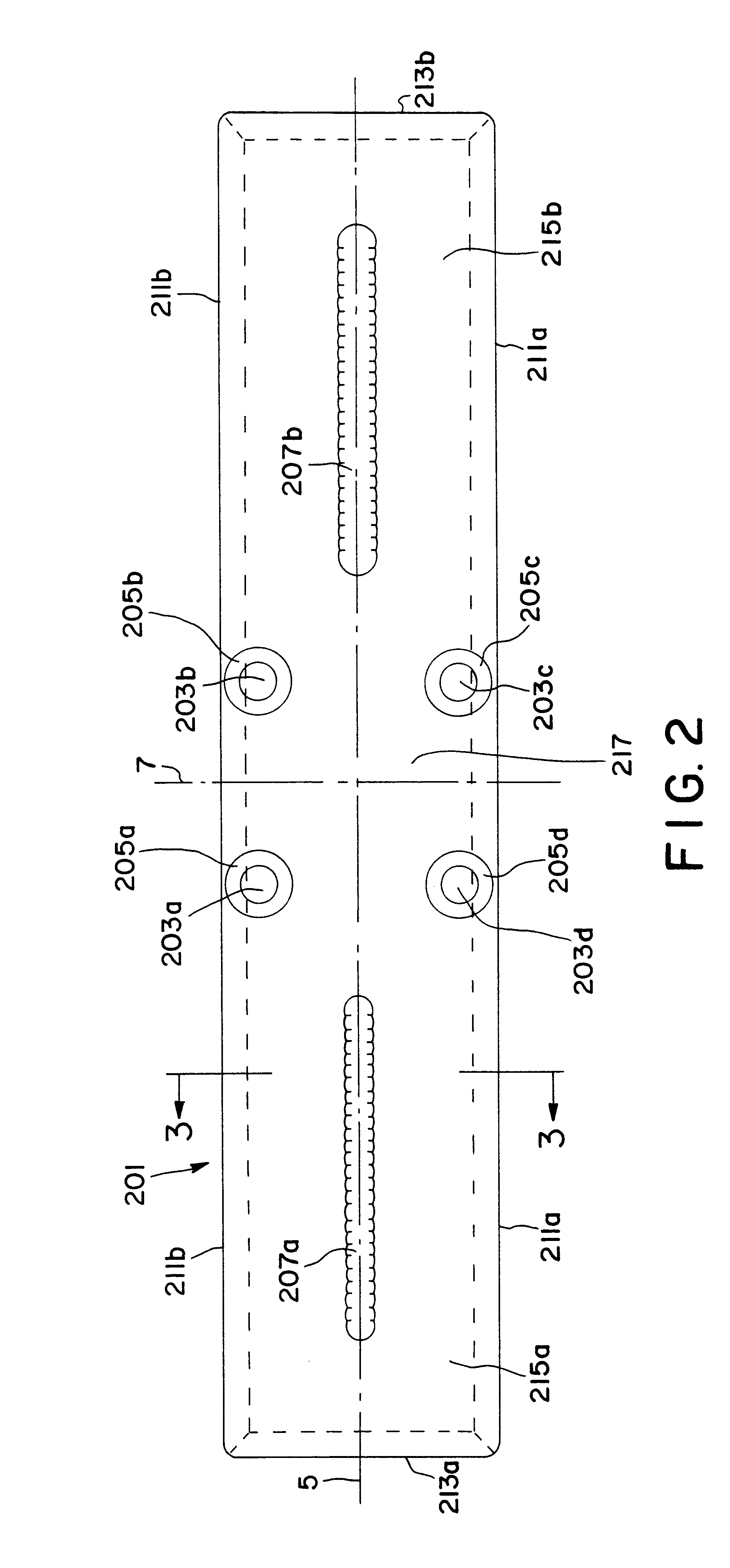
A boot binding system is shown for use especially on skiboards, having a binding plate, boot supports, bails, a lever, a resilient material, and a size adjustment locking mechanism. Boot supports and binding plate are complimentary shaped for slideable affixation to each, without requiring additional fasteners. A simple fastener locks the relative position of the boot support on the binding plate while also immobilizing any boot support motion. In the locked position, the fastener mates with counterbores in the binding plate's surface. The binding plate is rectangular in top view and its longitudinal edges have a chamfer, which complements a chamfer on the boot supports. The binding plate has mounting holes in its central region, which are used to affix the binding to a skiboard. Resilient material exists between the binding plate and the skiboard, thereby allowing the skiboard to flex more freely. The boot supports have slots to retain the bails. The lever also has a slot to accept a bail. The binding is simple to manufacture and assemble making it cost competitive for production. An alternate embodiment includes a version that eliminates the need for resilient material. A second alternate embodiment eliminates the central mount and mounts to the skiboard in the region of the boot supports.

Description

BACKGROUND--FIELD OF THE INVENTIONThis invention relates to snow sport bindings, and is specifically an improved non-safety release binding, which affixes a boot to a skiboard, snowboard, ski, or snow sports equipment.BACKGROUND--Discussion of Prior ArtEarly ski bindings provided various mechanisms to affix and detach a boot to a ski. Such bindings would require the user to willfully attach and detach the boot from the ski before and after use and did not employ any type of safety release mechanism. Numerous injuries to skiers' legs forced the development of safety release ski bindings. Many of these injuries are attributable to the long length of the ski. Modern safety release ski bindings employ sophisticated mechanisms to ensure proper safety release of the skiers' boot and minimize the likelihood of injury.The development of the snowboard has evidenced a different scenario in that the reduction of bodily injuries has not been correlated with safety release binding features. Henc...

Claims


Application Information

Patent Timeline
Patent Type & Authority Patents(United States)
IPC IPC(8): A63C9/00A63C10/08A63C10/22
CPCA63C10/08A63C10/22
Inventor CARON, JEFFREY E.SMITH, GEOFFREY W.
Owner CARON ALPINE TECH
Learn More