Containers

a technology for containers and containers, applied in the field of containers, can solve the problems of accumulating residual stresses in beams, reducing the weight of steel, and inability to deformation,

Inactive Publication Date: 2001-11-20
CLIVE SMITH COWLEY
View PDF20 Cites 42 Cited by
  • Summary
  • Abstract
  • Description
  • Claims
  • Application Information

AI Technical Summary

Problems solved by technology

However these were found too heavy and it is now more common for the beams to be fabricated from steel plate and sheet.
Thus, there can be a significant amount of heat generated by welding and cutting resulting in an accumulation of residual stresses in the beams.
Such deformation is not acceptable.
It has been suggested that the cause of the deformation is that the combined residual stre

Method used


Image

  • Containers
  • Containers
  • Containers

Examples


Embodiment Construction

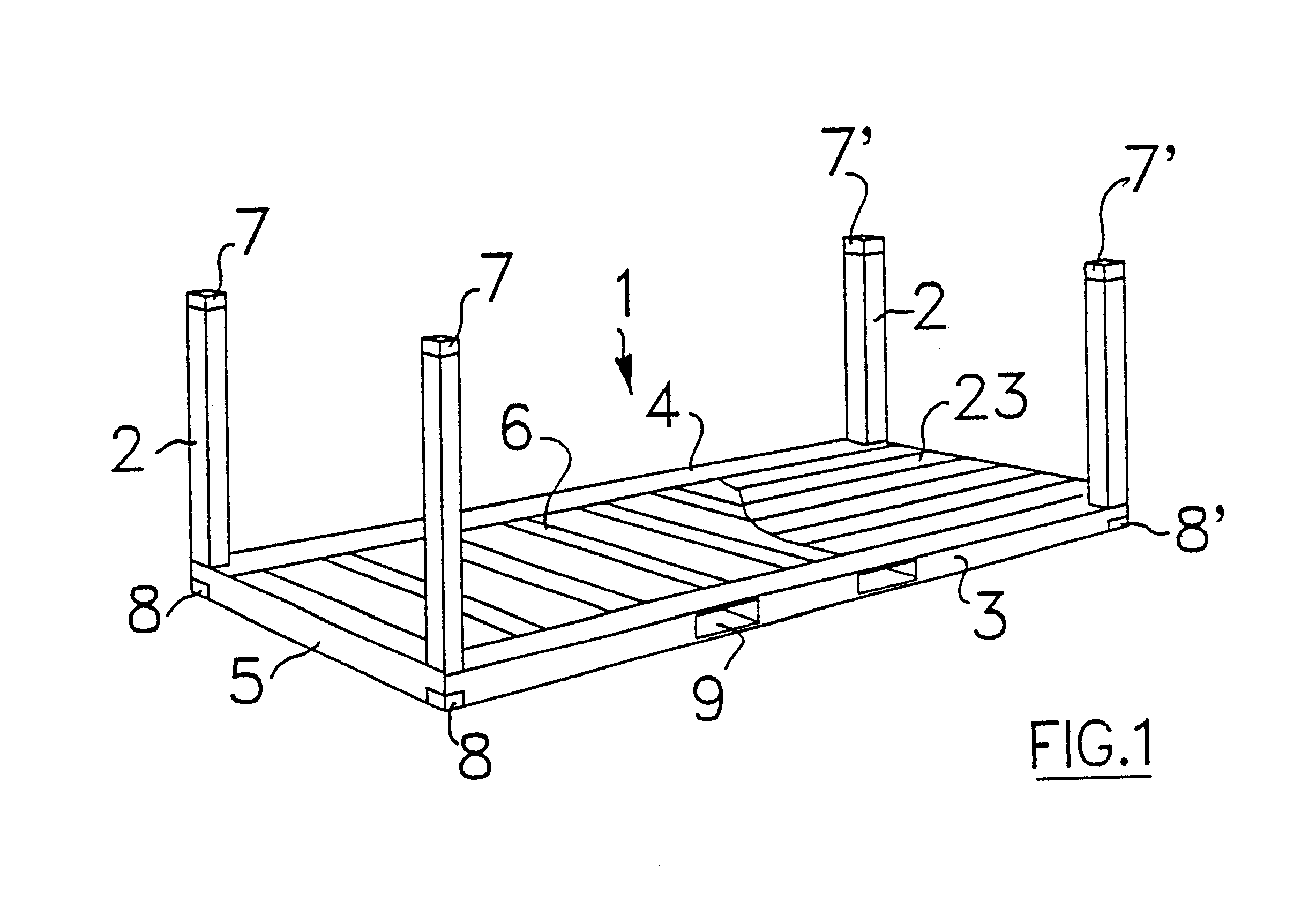
In FIG. 1 there is seen a typical platform-based container or flatrack 1 with corner posts 2 fixed in the erect position. There is a rectangular platform base 3 comprising a framework of longitudinal beams 4, one on each side, transverse end rails 5 and floor bearers 6. Floor timber 23 is fitted over the bearers 6 and cargo (not shown) laid on top of the timber 23 for carriage of the cargo.

At the top of the posts 2 are corner fittings 7, 7' and at the bottom fittings 8, 8' which are commonly located in a standardised geometric relationship to one another to enable standardised handling devices and other like containers to be connected to the fittings 7, 7', 8, 8'. Passing through the base 3 are tunnels 9 into which the tines of fork lift trucks can pass to lift the flatrack 1.

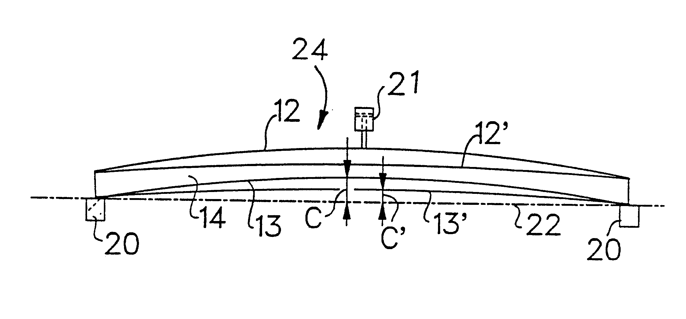
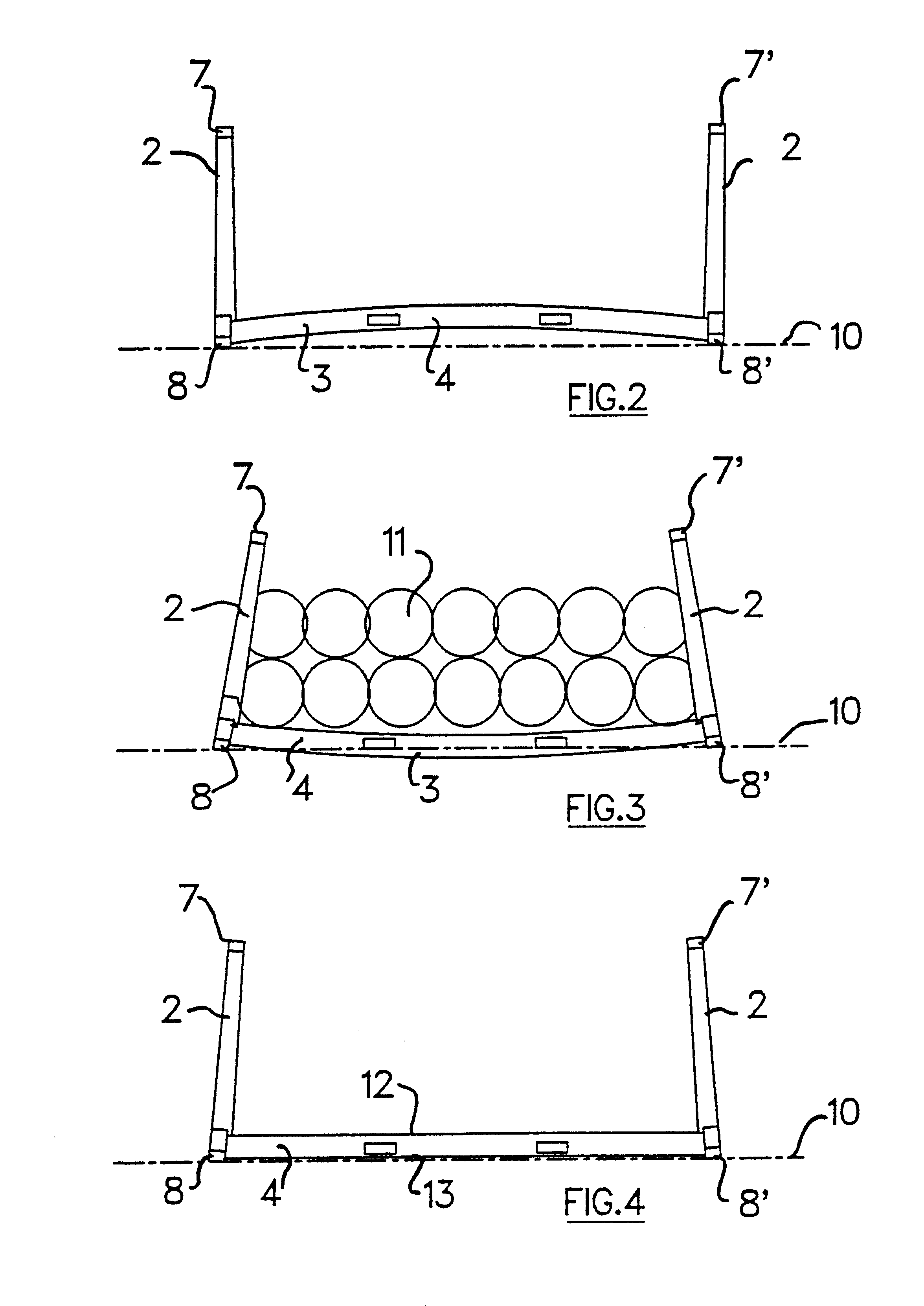
FIG. 2 shows a side elevation of flatrack 1. a dotted line 10 is shown to represent a surface which might be the ground, or the bed of a transport vehicle or the roof of another container. The fittings 8, 8' re...


PUM

PropertyMeasurementUnit
Deformation enthalpyaaaaaaaaaa
Residual stressaaaaaaaaaa

Abstract

A method of assembling a platform-based container comprising a base having at least one longitudinal beam, wherein the method comprises pre-loading the longitudinal beam, prior to the completion of the assembly of the container. The beam is then used in the assembly of the container, resulting in a container which no longer takes a permanent deformation under maximum load.

Description

I. BACKGROUNDIn the field of shipping containers there is a series of containers called platform-based containers comprising a rectangular platform base. Sometimes these have erect corner posts at either end and are then known as flatracks. The bases of the platforms comprise a framework of longitudinal beams and transverse members.Hot rolled I beams used to be used in the construction. However these were found too heavy and it is now more common for the beams to be fabricated from steel plate and sheet. The fabrication technique is to weld the pieces of steel together to form an I section beam similar to the earlier hot rolled type. Added to the beams are stake pockets, lashing devices, recesses for folding posts and so on. Thus, there can be a significant amount of heat generated by welding and cutting resulting in an accumulation of residual stresses in the beams.After the beam is built into the platform base, the base is fitted out with a deck, typically timber and thus presente...

Claims


Application Information

Patent Timeline
IPC IPC(8): B65D19/38E04C5/01E04C5/06
CPCB65D19/385E04C5/06Y10T29/49634Y10T29/49863Y10T29/49874B65D2519/00796
Inventor CLIVE-SMITH, MARTIN
Owner CLIVE SMITH COWLEY
Why Eureka
Try Eureka