
Changing the characteristics of an article-conveying belt surface on a running conveyor

a technology of article conveyor and belt surface, which is applied in the direction of conveyor parts, packaging, transportation and packaging, etc., can solve the problem that the plant is often incompatible with the other challenges

Inactive Publication Date: 2001-11-20
THE LAITRAM CORP
View PDF6 Cites 160 Cited by
  • Summary
  • Abstract
  • Description
  • Claims
  • Application Information

AI Technical Summary

Benefits of technology

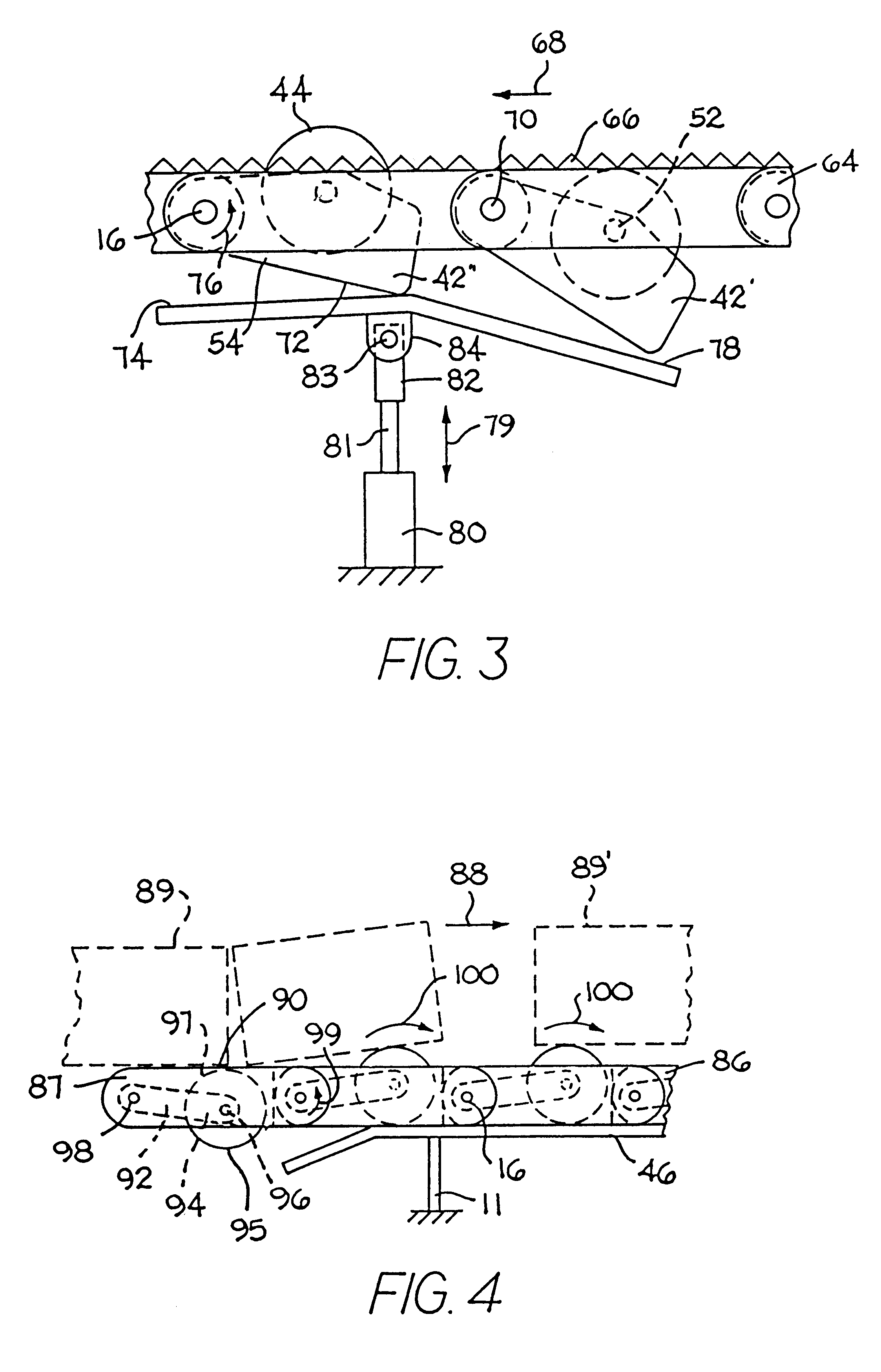
In one version, the movable assembly is a retractable assembly that includes a retractable element that is movable from a first retracted position within the opening and below the conveying surface to a second salient position above the conveying surface. The conveyor frame supports a bearing member close to the inner surface of the belt along a portion of the conveying path. The bearing member bears against the retractable assembly to urge the retractable element from the first retracted position to the second salient position to support conveyed articles from below. Thus, by positioning bearing members at strategic locations along the conveying path, one can "program" the belt to present a different characteristic to supported articles where needed.
According to yet another version, the retractable assembly includes an adjustable rotatable wheel below the inner surface of the belt. An adjustment control rack of predetermined length in the direction of belt travel is supported in the conveyor frame near the inner surface of the belt. The forward motion of the belt causes the wheel and the retractable element to rotate about an axis normal to the conveying surface as the wheel rides along the rack. The length of the rack determines the extent of the rotation of the retractable element. In one embodiment, the wheel includes a set of circumferentially arranged gear teeth. The rack includes a set of teeth that mesh with the wheel's teeth to rotate the retractable element to a known orientation. By selecting the length of the rack, the amount of rotation of the retractable element can be set for the application. In the case of a cylindrical roller, its axis of rotation relative to the direction of belt travel can be adjusted. In this way the conveyor can be set with the axis of rotation of the roller transverse to the direction of belt travel for low backline pressure or oblique for side-off transfer.
The bearing member may be realized in various ways according to the invention. In one version the bearing member is a flat wearstrip surface positioned to coact with the retractable assemblies in preselected zones to raise the retractable elements. The wearstrip could include a sloping portion that gradually bears against the retractable assemblies to prevent the retractable element from popping up too suddenly. In a more sophisticated version, the bearing member could be controlled by a mechanism, such as a pneumatically controlled bladder or cylinder that raises the bearing member on command. In conjunction with a control system, such a mechanism enables more control options.

Problems solved by technology

The response to one challenge confronting the article as it travels through the plant is often incompatible with the other challenges.
But this solution requires a number of different-style belts, more belt drive systems, and more plant space to handle the additional feet of belt, drive components, and transfer mechanisms required.

Method used


Image

  • Changing the characteristics of an article-conveying belt surface on a running conveyor
  • Changing the characteristics of an article-conveying belt surface on a running conveyor
  • Changing the characteristics of an article-conveying belt surface on a running conveyor

Examples


Embodiment Construction

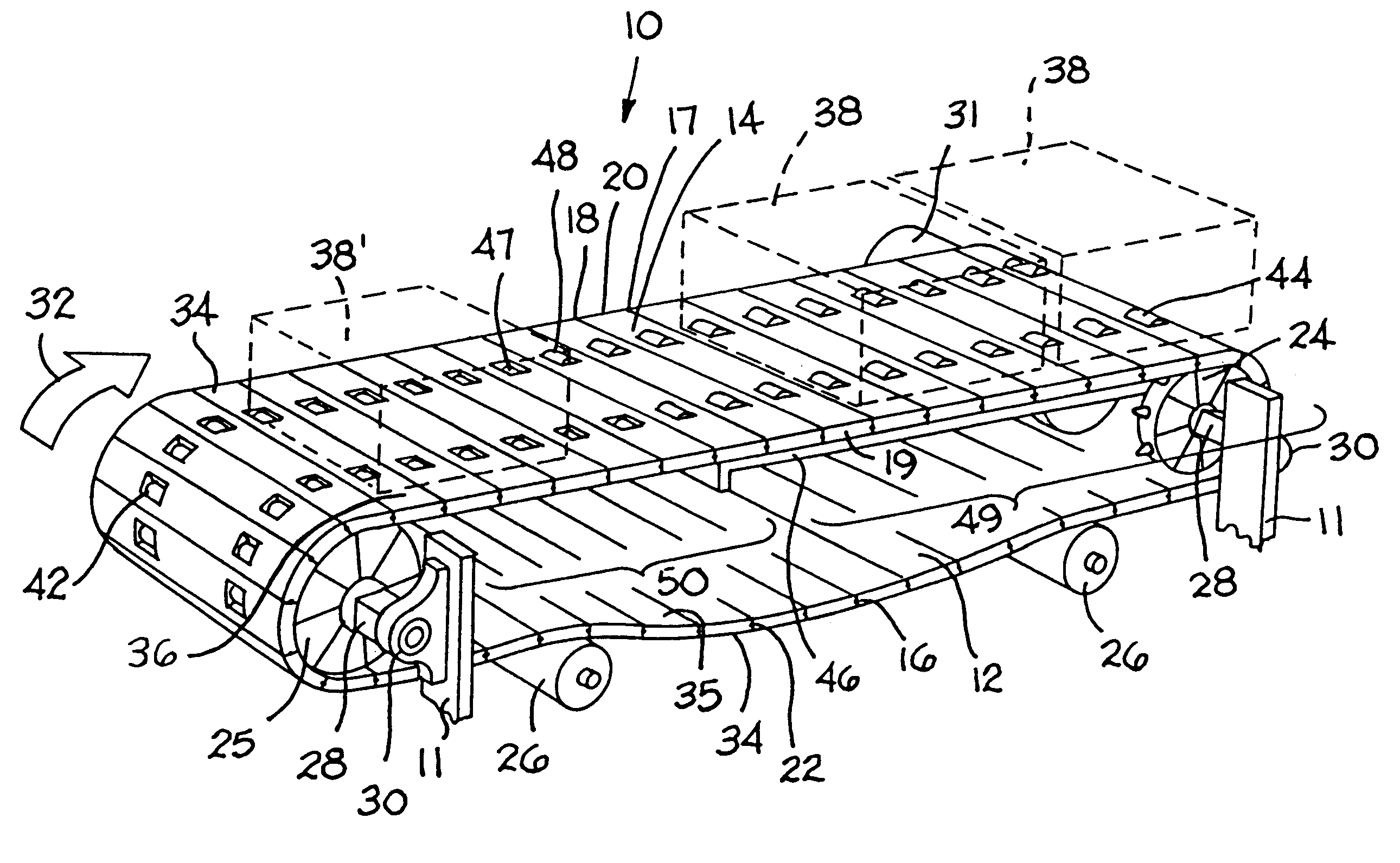
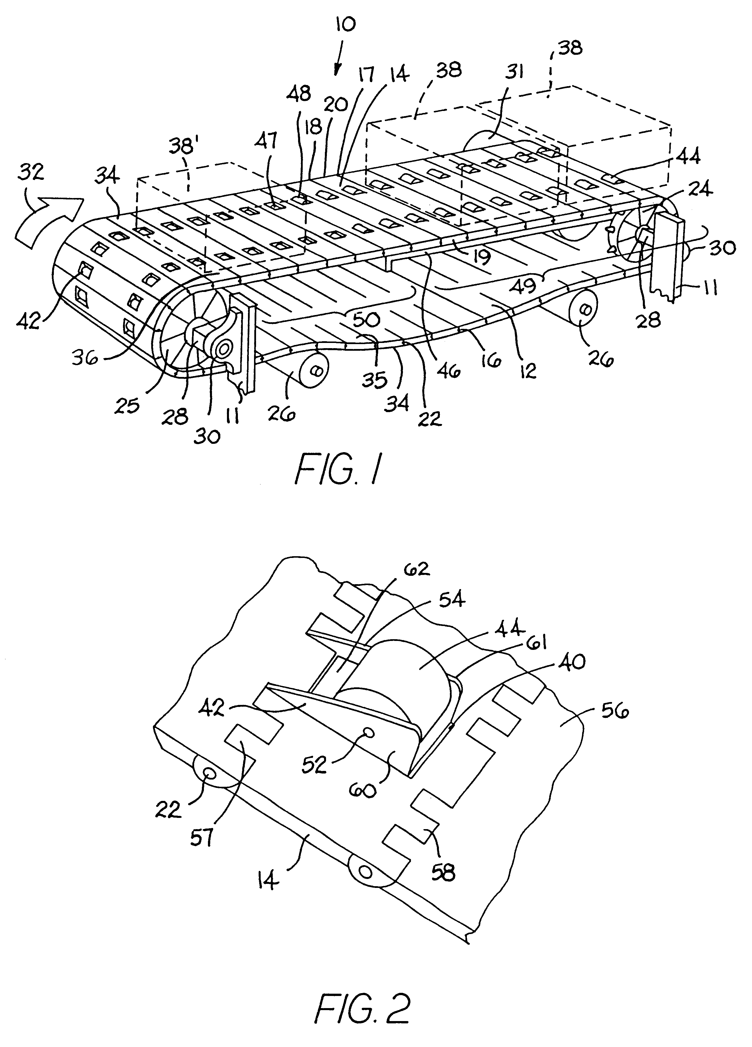
An exemplary conveyor having features of the invention is shown in FIG. 1. The conveyor 10 includes a conveyor frame 11 supporting a conveyor belt 12. The belt shown is in the form of an endless conveyor belt consisting of a series of rows 14 of belt modules linked together by hinge pins 16. Each row extends along the conveying path from a first end 17 to a second end 18 and across the width of the row from a first side edge 19 to a second side edge 20. Each row may comprise one or more belt modules. Hinge elements along the first and second ends of each row include aligned apertures 22 for a hinge pin acting as a journal to allow the belt to articulate about drive sprockets 24, idler sprockets 25, and returnway support rollers or drums 26.

The sprockets 24, 25 are mounted on shafts 28 rotatably supported by bearing blocks 30 at each end. A motor 31 drives the shaft 38 of the drive sprockets 24 to move the belt in the direction of belt travel indicated by arrow 32. (The motor could a...


PUM


Abstract

A belt conveyor whose article-conveying characteristics can be changed as the belt is running. The conveyor belt includes a plurality of movable assemblies supporting an article-supporting element and an adjustable element. The adjustable element coacts with an adjustment control element supported in the conveyor frame as the belt is running. The coaction causes the adjustable element to move the article-supporting element to provide a different article-conveying characteristic to articles supported at the conveying surface of the belt in zones defined by the adjustment control elements.

Description

1. Field of the InventionThe invention relates to article conveyors generally and, more particularly, to conveyors having an article-conveying surface with article-engagement characteristics that can be changed while the conveyor is running.2. Description of the Related ArtConveyor belts are used widely to transport articles through plants. During its odyssey through a plant, an article encounters a variety of challenges. For example, the article may need to descend from one level to a lower level or to climb from the lower level to a higher level. To give the article some traction on an incline or to prevent it from sliding out of control down a decline, conveyor belts with rubber or other high friction materials on the conveying surface are used. At other places in the plant, a number of articles must be accumulated because, for example, a downstream process is proceeding more slowly than an upstream process. To prevent the accumulating articles from crushing each other as the con...

Claims


Application Information

Patent Timeline
IPC IPC(8): B65G17/00B65G17/24B65G47/31
CPCB65G17/24B65G47/31B65G2201/02B65G2207/30
Inventor O'CONNOR, GERALD M.LAPEYRE, ROBERT S.GREVE, CHRISTOPHER G.
Owner THE LAITRAM CORP
Learn More