Piezoelectric/Electrostrictive device
a technology of electro-electrostrictive device and movable portion 24, which is applied in piezoelectric/electrostrictive/magneto-strictive device, piezoelectric/electrostriction/magneto-striction machine, electrical apparatus, etc., and can solve the problems of low mechanical strength, inferior handling, and small operation quantity of the movable portion 24
- Summary
- Abstract
- Description
- Claims
- Application Information
AI Technical Summary
Problems solved by technology
Method used
Image
Examples
third embodiment
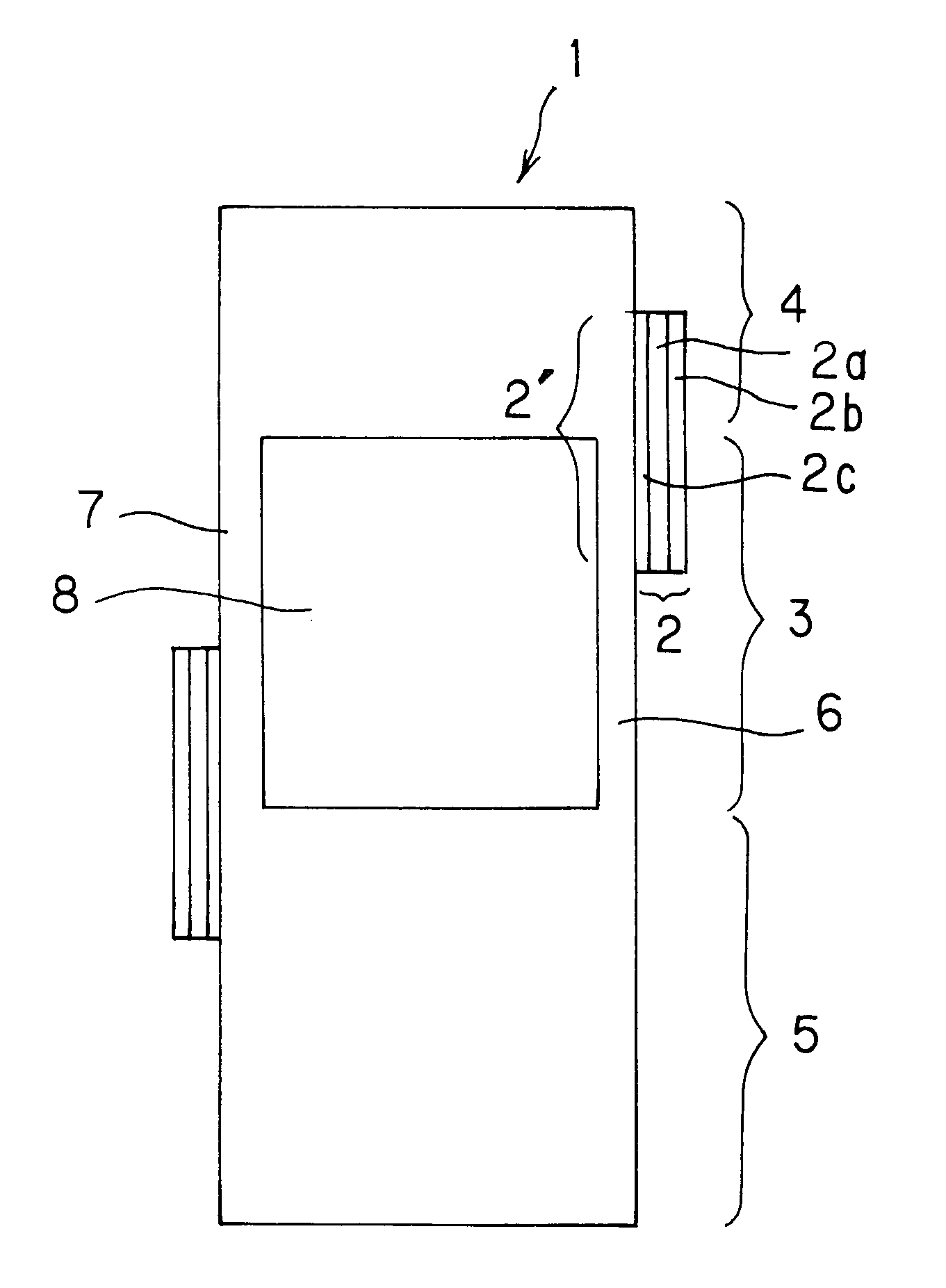
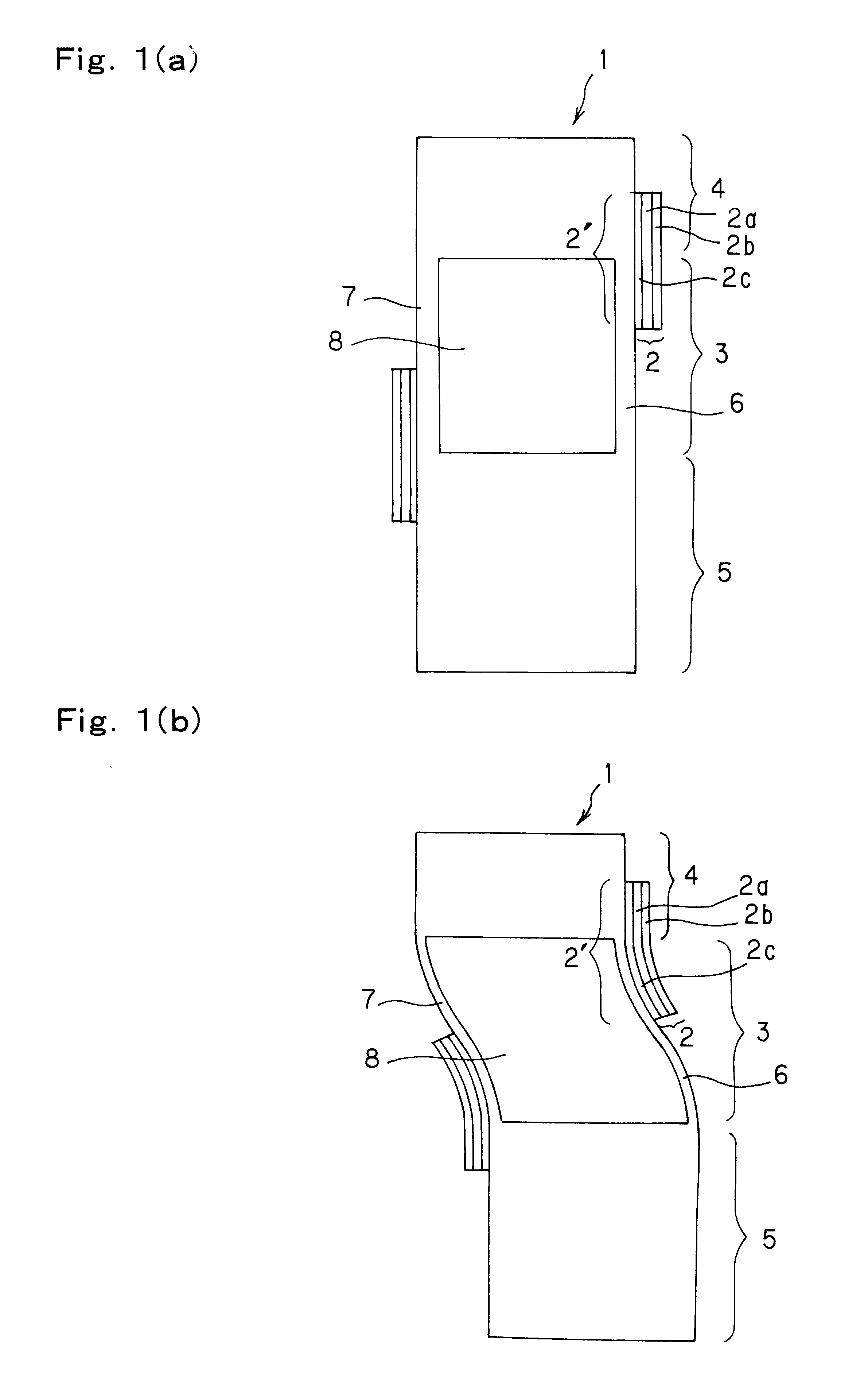
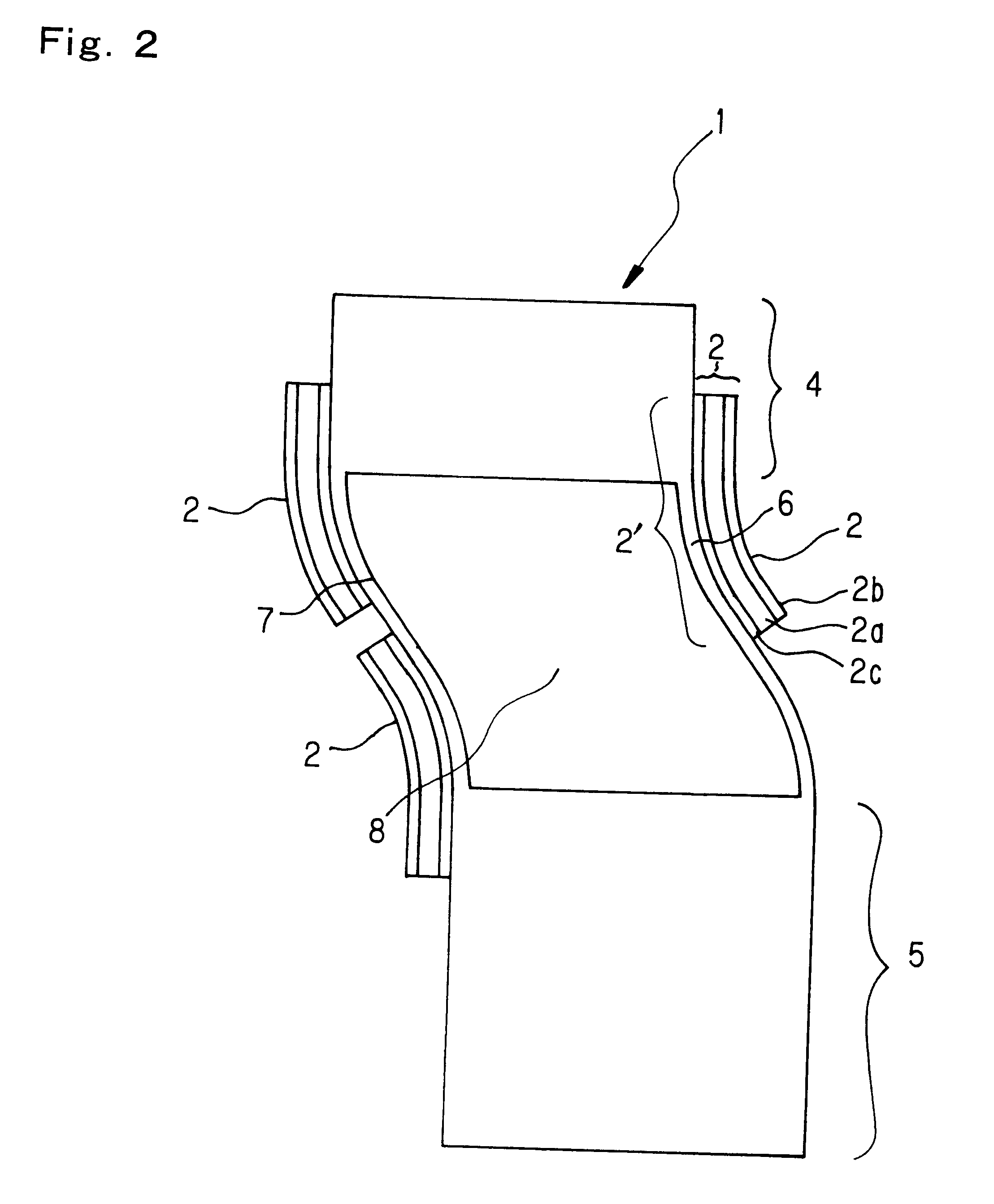
In a third embodiment, as shown in FIGS. 3 (a) and (b), a device is mounted with two each, four in total, piezoelectric / electrostrictive elements respectively comprising a pair of electrodes 2b, and 2c and a piezoelectric / electrostrictive film 2a mutually opposed on the same thin plate portions 6, and 7, and therefore four fulcrums are available for a displacement. So, if elements positioned at least in diagonal directions across a hole mutually have the same functions, driving force can be doubled by simultaneously driving the same, thus the driving force can be efficiently converted into a displacement in addition to remarkable increase in displacement quantity. Further, by forming piezoelectric / electrostrictive elements having mutually different strain directions formed on the same driving portion (thin plate portion), the displacement of the thin plate portion due to the strain such as expansion and / or contraction can be carried by respective piezoelectric / electrostrictive eleme...
example 1
LAMINATION EXAMPLE 1
After sequentially laminating a ceramic green sheet (hereinafter referred to as "GS") 1 for the thin plate, GS1 having a hole formed thereon (hereinafter referred to as "with a hole"), GS2 with a hole, GS3 with a hole, GS4 with a hole, and GS2 for the thin plate, all shown in FIG. 19, the lamination is subjected to a compression to produce an integrally laminated ceramic green body.
example 2
LAMINATION EXAMPLE 2
Step 1: After laminating GS1 for the thin plate over GS1 with a hole, the lamination is subjected to compression to produce an integrally laminated ceramic green body.
Step 2: After laminating GS4 with a hole over GS2 for the thin plate, the lamination is subjected to compression to produce an integrally laminated ceramic green body.
Step 3: After sequentially laminating the integrally laminated ceramic green body obtained in step 1, GS2 with a hole, GS3 with a hole, and an integrally laminated ceramic green body obtained in step 2, the lamination is subjected to compression to produce an integrally laminated ceramic green body.
PUM
 Abstract
Description
Claims
Application Information
 - R&D
- Intellectual Property
- Life Sciences
- Materials
- Tech Scout
- Unparalleled Data Quality
- Higher Quality Content
- 60% Fewer Hallucinations
Browse by: Latest US Patents, China's latest patents, Technical Efficacy Thesaurus, Application Domain, Technology Topic, Popular Technical Reports.
© 2025 PatSnap. All rights reserved.Legal|Privacy policy|Modern Slavery Act Transparency Statement|Sitemap|About US| Contact US: help@patsnap.com


