Push-to-connect tubing fitting

Inactive Publication Date: 2002-01-01
INT TRUCK INTPROP LLC
View PDF34 Cites 40 Cited by
  • Summary
  • Abstract
  • Description
  • Claims
  • Application Information

AI Technical Summary

Benefits of technology

As a result,--an object of the present invention is to provide a fitting which allows quick, easy assembly and disassembly of a tubing connection without the use of tools and to further ensure that the tubing cannot be mecha

Problems solved by technology

Thus it is not possible to insert the tubing into the fitting tar enough to mechanically enga

Method used


Image

  • Push-to-connect tubing fitting
  • Push-to-connect tubing fitting
  • Push-to-connect tubing fitting

Examples


Embodiment Construction

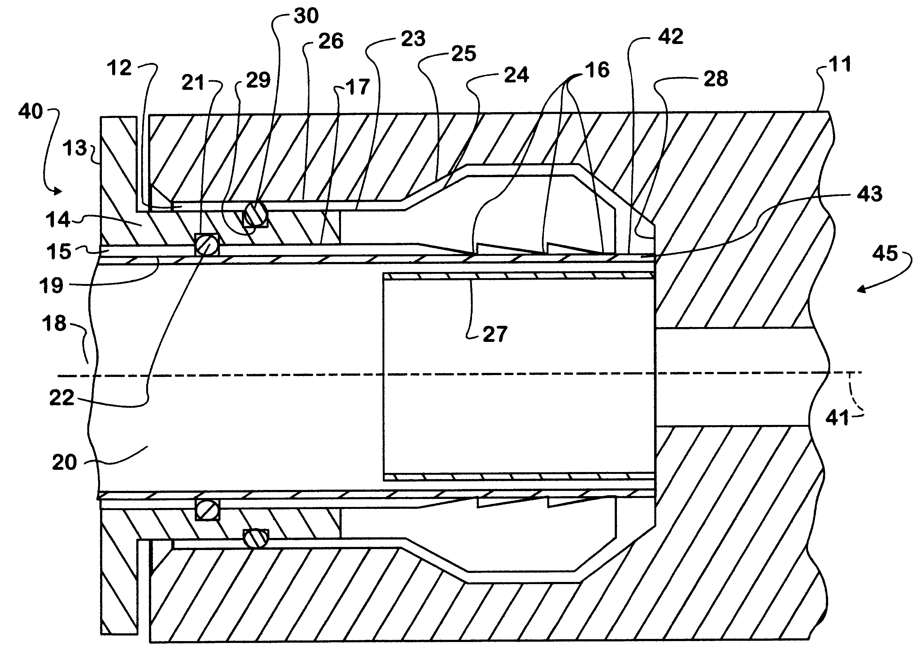
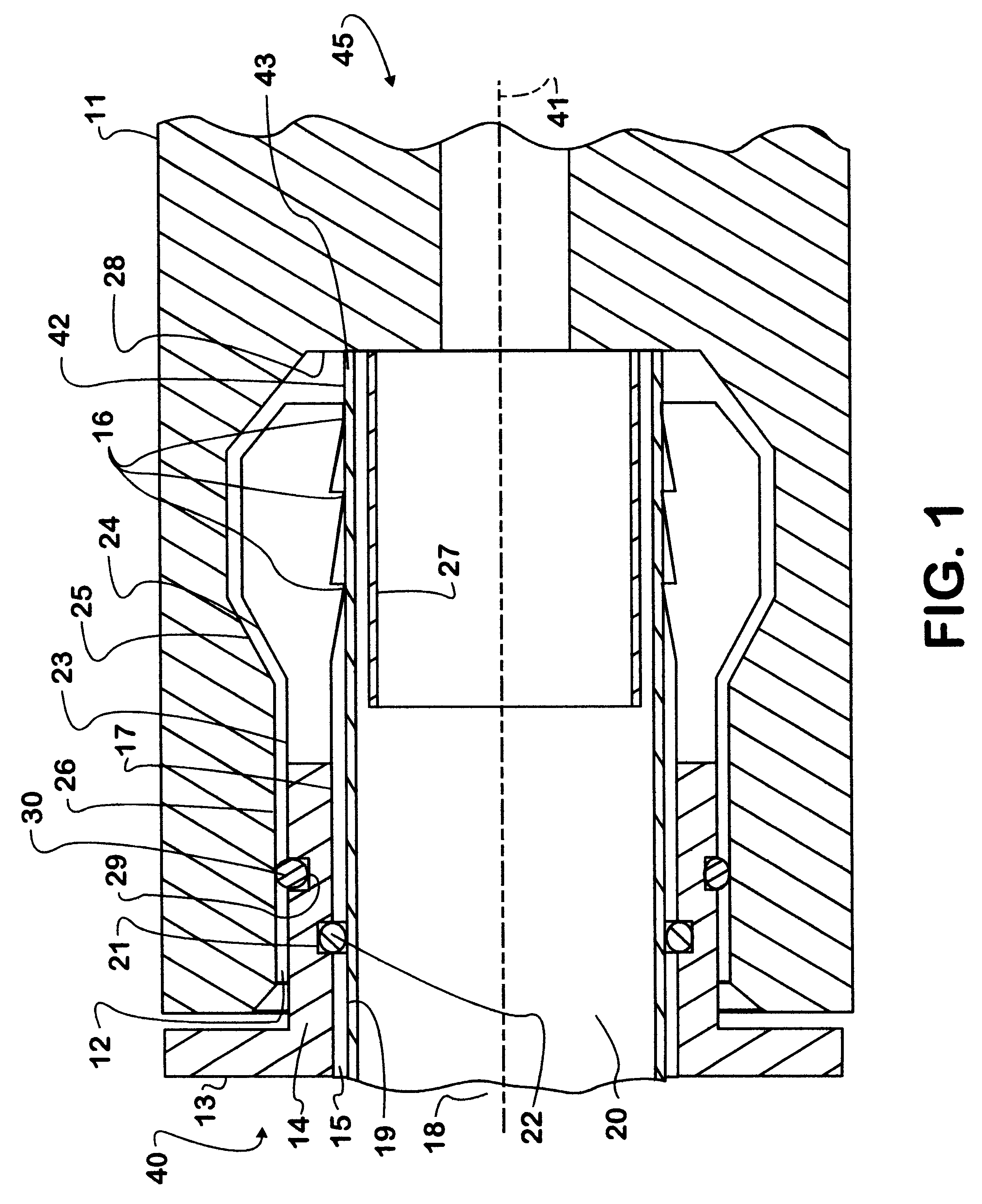
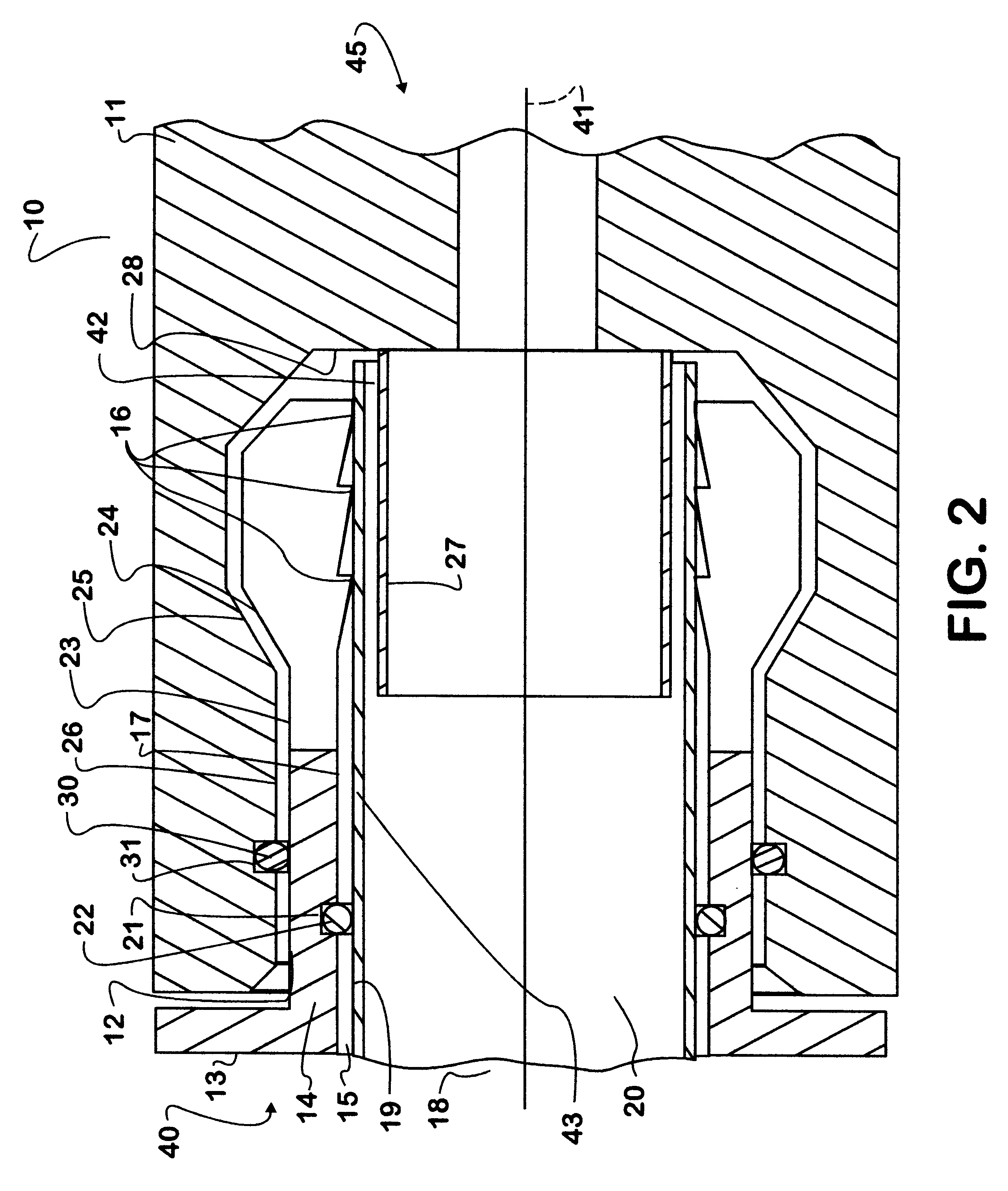
There is shown in FIGS. 1 and 2 a push to connect tubing fitting in accordance with this invention. In the most basic form of the invention the fitting 10 has a body 11 which defines a bore 12 parallel to the axis 41 of the fitting 10. A collett 13 is disposed within the bore 12 of the body 11 of the fitting 10. The collett 13, has an outer wall 14, which defines a cylindrical bore 15 through the collett 13. Tubing gripping devices 16 are disposed on an inner surface 17 of the bore 15 of the collett 13. A sealing device 22 is positioned co-axially within the bore 15 of the collett 13, at a point closer to an outer end 40 of the fitting 10 than are the tubing gripping devices 16. Another sealing device 30 is positioned between an outer surface 23 of the collett 13 and an inner surface 26 of the bore 12 of the body 11. Thus when tubing 20 is inserted into the fitting 10 it first engages the sealing device 22 and after further insertion engages the tubing gripping devices 16.

The sealin...


PUM


Abstract

A push-to-connect tubing fitting which has a body, a collett with tubing gripping teeth that engage the tubing, and sealing devices. The collett is disposed within a bore in the body of the fitting. The collett has tubing gripping teeth on its inner bore which mechanically engage the outer surface of the tubing. A first sealing device is positioned within an inner bore of the collett at a point closer to the tubing insertion opening of the collett than are the tubing gripping teeth. This first sealing device seals the tubing to the collett. A second sealing device is disposed between the collett and the body. This second sealing device seals the collett to the body of the fitting and effectively completes the seal between the tubing and the body.

Description

This invention relates to an improved-push-to connect tubing fitting for engaging nylon tubing or tubing of like material. More specifically, the improved push to connect tubing fitting seals the tubing connection prior to mechanical engagement of the tubing to the fitting Upon insertion in the fitting, the tubing engages a sealing means prior to engaging the tubing gripping devices of the collett.PRIOR ARTThe purpose of the prior art push-to-connect tubing fittings is to allow assembly and disassembly of tubing connections without tools and as rapidly as possible. The tubing has a soft exterior and is circular in cross section. An example of a prior art tubing fitting with tubing assembled within the fitting is shown in FIG. 5. The prior art fittings 10 had a body 11 with a bore 12 in it. A collett 13 was positioned within the bore 12 of the body 11 to mechanically engage the nylon tubing 20 upon its insertion. The collett 13 had a bore 15 extending along the same axis as the bore ...

Claims


Application Information

Patent Timeline
IPC IPC(8): F16L37/098F16L37/092F16L37/00
CPCF16L37/0925F16L37/0926F16L37/0927
Inventor OSTERKIL, ALAN D.
Owner INT TRUCK INTPROP LLC
Why Eureka
Try Eureka